Table of Contents
Advertisement
Quick Links
Advertisement
Table of Contents

Related Manuals for Circutor DHC-96 Vac


Summary of Contents for Circutor DHC-96 Vac
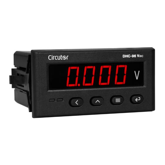
- Page 1 AC Voltmeter DHC-96 Vac INSTRUCTION MANUAL (M224B01-03-20A)
- Page 2 DHC-96 Vac Instruction Manual...
-
Page 3: Safety Precautions
CIRCUTOR, SA reserves the right to modify features or the product manual without prior notifi cation. DISCLAIMER CIRCUTOR, SA reserves the right to make modifi cations to the device or the unit specifi ca- tions set out in this instruction manual without prior notice. -
Page 4: Table Of Contents
DHC-96 Vac CONTENTS SAFETY PRECAUTIONS ��������������������������������������������������������������������������������������������������������������������������������������� 3 DISCLAIMER ���������������������������������������������������������������������������������������������������������������������������������������������������������� 3 CONTENTS ������������������������������������������������������������������������������������������������������������������������������������������������������������� 4 REVISION LOG ������������������������������������������������������������������������������������������������������������������������������������������������������� 6 SYMBOLS ��������������������������������������������������������������������������������������������������������������������������������������������������������������� 6 1�- VERIFICATION UPON RECEPTION ����������������������������������������������������������������������������������������������������������������� 7 2�- PRODUCT DESCRIPTION �������������������������������������������������������������������������������������������������������������������������������� 7 3�- DEVICE INSTALLATION ����������������������������������������������������������������������������������������������������������������������������������� 8 3�1�- PRIOR RECOMMENDATIONS������������������������������������������������������������������������������������������������������������������ 8 3�2�- INSTALLATION �����������������������������������������������������������������������������������������������������������������������������������������... - Page 5 DHC-96 Vac 6�3�4�- REMOTE CONTROL OUTPUT (Relay output) ����������������������������������������������������������������������������� 35 6�3�5�- DEVICE CONFIGURATION VARIABLES �������������������������������������������������������������������������������������� 36 7�- TECHNICAL FEATURES ������������������������������������������������������������������������������������������������������������������������������� 38 8�- MAINTENANCE AND TECHNICAL SERVICE ����������������������������������������������������������������������������������������������� 41 9�- GUARANTEE �������������������������������������������������������������������������������������������������������������������������������������������������� 41 10�- CE CERTIFICATE ����������������������������������������������������������������������������������������������������������������������������������������� 42 ANNEX A�- CONFIGURATION MENU ����������������������������������������������������������������������������������������������������������������� 45...
-
Page 6: Revision Log
DHC-96 Vac REVISION LOG Table 1: Revision log� Date Revision Description 11/18 M224B01-03-18A Initial Version Change in the following sections: 01/19 M224B01-03-19A 6.1. - 7. - 10. Change in the following sections: 02/20 M224B01-03-19A 2. - 5.1. - 5.3.2. - 5.3.3. - 5.4.5. - 5.4.6. - 6.1. - 6.3.1. - 6.3.2. - 6.3.3. -
Page 7: 1�- Verification Upon Reception
CIRCUTOR's after-sales service. 2�- PRODUCT DESCRIPTION The DHC-96 Vac is a device designed to measure and display the voltage and the frequency AC single-phase. The device has 6 programmable voltage scales: 63.5V, 100V, 110V, 230 V, 380 V and 480 V. -
Page 8: 3�- Device Installation
The DHC-96 Vac device must be installed by authorised and qualified staff. The power supply plug must be disconnected and measuring systems switched off before handling, altering the connections or replacing the device. -
Page 9: 3�2�- Installation
DHC-96 Vac 3.2.- INSTALLATION Terminals, opening covers or removing elements can expose parts that are hazardous to the touch while the device is powered. Do not use the device until it is fully installed. The device should be installed inside an electric panel or enclosure, and panel-mounted. -
Page 10: 3�3�- Device Terminals
DHC-96 Vac 3.3.- DEVICE TERMINALS Table 4:List of terminals of the DHC-96 Vac� Device terminals 1 : L, Auxiliary power supply. 31: Alarm output 2, relay (Common) 2: N, Auxiliary power supply. 32: Alarm output 2, relay (NO) 11: Voltage measurement input... -
Page 11: 3�4�- Connection Diagram
70 59 RS-485 Salida de relés Relay output Alimentación Auxiliar Power Supply Figure 4: Voltage measurement DHC-96 Vac� If the voltage being measured is higher than the rated input voltage, a voltage transformer should be connected to the device. Instruction Manual... -
Page 12: 4�- Operation
Display 00000 Keyboard Figure 5: Display DHC-96� 4.2.- KEYBOARD FUNCTIONS The DHC-96 Vac features 4 keys to display and configure the device, Figure 5 Table 5: Keyboard functions� Keystroke Previous screen In the configuration menu:... -
Page 13: 4�3�- Relay Outputs
(See “5.4.- RELAY OUTPUT 1” and “5.5.- RELAY OUTPUT 2”) 4.6.- DISPLAY The DHC-96 Vac features 4 display screens, Table 6 Use the keys to browse the screens. Table 6: Display menu�... - Page 14 DHC-96 Vac Table 6 (Continuation) : Display menu� Display menu 50.00 Frequency Status of digital inputs: , status of the digital input 1: flashes when the input is activated , status of the digital input 2: flashes when the input is activated...
-
Page 15: 5�- Configuration
Con guration of the display Software version Figure 7: Configuration menu of the DHC-96 Vac� From any screen of the configuration menus, if no key is pressed for 4 minutes, the device leaves the configuration menu and returns to the display screen. - Page 16 DHC-96 Vac rEAd , key to access the configuration menu in the display On the screen, press the mode, i.e., the configuration parameters cannot be modified. rEAd On the screen, press the keys to access the configuration menu in the programming mode, i.e., the configuration parameters can be modified.
-
Page 17: 5�1�- Configuration Of The Input
DHC-96 Vac 5.1.- CONFIGURATION OF THE INPUT , shows the main screen of the input configuration menu, from which the primary Figure 10 voltage and secondary voltage are configured. inPt Figure 10: Input configuration menu, main screen. Press the key to open the configuration menu. -
Page 18: 5�1�2�- Units Of The Primary Voltage
DHC-96 Vac To validate the data, press the key. Use the keys to browse the configuration screens of the menu. 5�1�2�- UNITS OF THE PRIMARY VOLTAGE This screen is used to configure the units of the primary voltage. Unt. i... -
Page 19: 5�1�4�- Save Configuration
DHC-96 Vac 5�1�4�- SAVE CONFIGURATION To save the configuration of the device, press the key, until the main screen of the input configuration menu is opened, Figure 10 Press the key again to show the validation screen. SAuE Use the ,key to browse the different options: , exit the configuration without saving the changed values. -
Page 20: 5�2�1�- Modbus Address
DHC-96 Vac 5�2�1�- MODBUS ADDRESS This screen is used to configure the modbus address of the device. Addr 0001 Use the , key to modify the value of the flashing digit When the desired value is shown on the screen, press the key to skip the digit. -
Page 21: 5�2�4�- Save Configuration
DHC-96 Vac n.8.1 , no parity, 8 data bits, 1 stop bit o.8.1 , odd parity, 8 data bits, 1 stop bit E.8.1, even parity, 8 data bits, 1 stop bit n.8.2 , no parity, 8 data bits, 2 stop bit To validate the data, press the key. -
Page 22: 5�3�1�- Type Of Output
DHC-96 Vac A0-1 nodE 4-20 0.000 5.000 Figure 15:Analog output menu� 5�3�1�- TYPE OF OUTPUT In this screen the output type of the analog output is configured nodE 4-20 Use the keys at the same time to configure the value. -
Page 23: 5�3�3�- Reading For The End Of The Analog Output
DHC-96 Vac When the desired value is shown on the screen, press the key to skip the digit. Minimum configuration value: 0.000 Maximum configuration value: 0.5 x A. Note : The value of variable A varies depending on the secondary voltage programmed, see Table 7. -
Page 24: 5�3�4�- Save Configuration
DHC-96 Vac 5�3�4�- SAVE CONFIGURATION To save the configuration of the device, press the key, until the main screen of the input configuration menu is opened, Figure 10 Press the key again to show the validation screen. SAuE Use the ,key to browse the different options: , exit the configuration without saving the changed values. -
Page 25: 5�4�- Relay Output 1
DHC-96 Vac 5.4.- RELAY OUTPUT 1 , shows the main screen of the configuration menu of relay output 1. Figure 16 do-1 Figure 16: Configuration menu of relay output 1, main screen. Press the key to open the setup menu. -
Page 26: 5�4�2�- Relay Pulse Duration
DHC-96 Vac , relay output 1 is disabled. , remote control output. , alarm output. To validate the data, press the key. Use the keys to browse the configuration screens of the menu. 5�4�2�- RELAY PULSE DURATION The alarm relay can behave in 2 different ways: 1�- The relay is activated when the alarm is triggered and is deactivated when the alarm... -
Page 27: 5�4�4�- Connection Delay
DHC-96 Vac U--H , Active alarm when the voltage is higher than the alarm value. F--L , Active alarm when the frequency is less than the alarm value. U--L , Active alarm when the voltage is less than the alarm value. -
Page 28: 5�4�6�- Hysteresis
DHC-96 Vac 0.000 uALE Use the , key to modify the value of the flashing digit When the desired value is shown on the screen, press the key to skip the digit. Minimum configuration value: U--H, U--L, di1H, di2H,di1L, di2L 000.0 For alarm parameters:... -
Page 29: 5�4�7�- Save Configuration
DHC-96 Vac 5�4�7�- SAVE CONFIGURATION To save the configuration of the device, press the key until the main screen of the relay output 1 configuration menu is opened, Figure 16 Press the key again to show the validation screen. SAuE... -
Page 30: 5�6�1�- Password Off Access
DHC-96 Vac 0001 CodE LiGH 120.0 Figure 20:Configuration menu of the display. 5�6�1�- PASSWORD OFF ACCESS This screen is used to configure the value of the password used to access the configuration menu in the programming mode. 0000 CodE Use the... -
Page 31: 5�6�3�- Light Alarm
DHC-96 Vac 5�6�3�- LIGHT ALARM If the voltage value measured by the device is higher than a % of the nominal value, the device can make the digits on the display start flashing, in the form of a light alarm. -
Page 32: 6�- Rs-485 Communications
DHC-96 Vac 6�- RS-485 COMMUNICATIONS The DHC-96 devices have one RS-485 communications port,with communications protocols: MODBUS RTU ® . 6.1.- CONNECTIONS The RS-485 cable must be wired with twisted pair cable with mesh shield, with a maximum distance between the DHC-96 and the master device of 1200 metres. -
Page 33: 6�2�- Modbus Protocol
DHC-96 Vac 6.2.- MODBUS PROTOCOL In the Modbus protocol, the DHC-96 device uses the RTU (Remote Terminal Unit) mode. The Modbus functions implemented in the device are as follows: Function 0x01: Reading a relay. Function 0x02: Reading input status. Function 0x03 and 0x04: Reading integer registers. -
Page 34: 6�3�- Modbus Commands
DHC-96 Vac Response: Initial Address Function Relay action Register 0000 FF00 8C3A 6.3.- MODBUS COMMANDS 6�3�1�- MEASUREMENT VARIABLES AND DEVICE STATUS All the addresses of Modbus memory are in Hexadecimal. For these variables is implemented the Function 0x03 and 0x04. -
Page 35: 6�3�3�- Digital Inputs
DHC-96 Vac 6�3�3�- DIGITAL INPUTS All the addresses of Modbus memory are in Hexadecimal. For these variables is implemented the Function 0x02� Table 12: Modbus memory map (Table 4) Parameter Format Address Digital input 0000 The format of the parameter is shown in Table 13: Table 13:Format of the variables : Digital inputs�... -
Page 36: 6�3�5�- Device Configuration Variables
DHC-96 Vac 6�3�5�- DEVICE CONFIGURATION VARIABLES All the addresses of Modbus memory are in Hexadecimal. For these variables is implemented the Function 0x10� 6.3.5.1. Configuration of the input Table 17:Modbus memory map : Configuration of the input Configuration of the input... - Page 37 DHC-96 Vac 6�3�5�4� Relays outputs Table 20:Modbus memory map : Relay outputs� Relay outputs Variable Format Address Valid data margin 0: output is disabled. Relay 1 mode 1: alarm output Relay 2 mode 2: remote control output. Relay 1 pulse duration 0 ...
-
Page 38: 7�- Technical Features
DHC-96 Vac 7�- TECHNICAL FEATURES AC Power supply 80 ... 270 V ~ Rated voltage Frequency 50 / 60 Hz Consumption 3.1 ... 5.4 VA Installation category CAT III 300 V DC Power supply Rated voltage 80 ... 270 V 18 ... - Page 39 DHC-96 Vac RS-485 communications Communications protocol Modbus RTU Baud rate 2400 - 4800 - 9600 - 19200 bps Data bits Stop bits 1 - 2 Parity without, even, odd User interface Display LED 5 digits Keyboard 4 keys Environmental features Operating temperature -40ºC ...
- Page 40 DHC-96 Vac 10(max) 68.5 81.2 Figure 22: Dimensions of the DHC-96� Instruction Manual...
-
Page 41: 8�- Maintenance And Technical Service
• CIRCUTOR accepts no liability due to the possible damage to the unit or other parts of the installation, nor will it cover any possible sanctions derived from a pos- sible failure, improper installation or “improper usage”... -
Page 42: 10�- Ce Certificate
DHC-96 Vac 10�- CE CERTIFICATE Instruction Manual... - Page 43 DHC-96 Vac Instruction Manual...
- Page 44 DHC-96 Vac Instruction Manual...
-
Page 45: Annex A�- Configuration Menu
Alarm parameter di2l diil F--L U--L dELy 0010 Connection delay uALE 000.0 Alarm value Hysteresis 000.5 CodE 0001 Password o access Brightness of the LiGH display 120.0 Light alarm Software version 3021 Figure 23:Configuration menu DHC-96 Vac. Instruction Manual... - Page 46 CIRCUTOR, SA Vial Sant Jordi, s/n 08232 -Viladecavalls (Barcelona) Tel.: (+34) 93 745 29 00 - Fax: (+34) 93 745 29 14 www.circutor.com central@circutor.com...
Need help?
Do you have a question about the DHC-96 Vac and is the answer not in the manual?
Questions and answers