
Subscribe to Our Youtube Channel
Related Manuals for ESAB CIGWELD WeldSkill 100 MIG


Summary of Contents for ESAB CIGWELD WeldSkill 100 MIG
- Page 1 WeldSkill 100, 135, 150 MIG WARRANTY* WARRANTY* 100A 135A 150A 0.8mm MAX 0.8mm MAX P/N: W1004100 P/N: W1004135 P/N: W1004150 Version No: AD Issue Date: 08-10-2019 Manual No: 0-5129...
- Page 2 YOU ARE IN GOOD COMPANY! The Brand of Choice for Contractors and Fabricators Worldwide. CIGWELD is a Market Leading Brand of Arc Welding Products for ESAB. We are a mainline supplier to major welding industry sectors in the Asia Pacific and emerging global markets including; Manufacturing, Construction, Mining, Automotive, Engineering, Rural and DIY.
- Page 3 While the information contained in this Manual represents the Manufacturer’s best judgement, the Manufacturer assumes no liability for its use. Operating Manual Number 0-5129 for: Cigweld WeldSkill 100 Mig Welding Machine Part Number W1004100 Cigweld WeldSkill 135 Mig Welding Machine...
-
Page 4: Table Of Contents
TABLE OF CONTENTS SECTION 1: ARC WELDING SAFETY INSTRUCTIONS AND WARNINGS ........1-1 1.01 Arc Welding Hazards ..................1-1 1.02 PRINCIPAL SAFETY STANDARDS ..............1-5 1.03 DECLARATION OF CONFORMITY ..............1-6 SECTION 2: INTRODUCTION ..................2-1 2.01 How To Use This Manual ................2-1 2.02 Equipment Identification ................. - Page 5 TABLE OF CONTENTS SECTION 4: OPERATION ................... 4-1 4.01 WeldSkill 100 Mig Power Source Controls, Indicators and Features....4-1 4.02 WeldSkill 135 Mig Power Source Controls, Indicators and Features....4-2 4.03 WeldSkill 150 Mig Power Source Controls, Indicators and Features....4-3 4.04 Cigweld MIG Wire Selection Chart ..............
-
Page 7: Arc Welding Safety Instructions And Warnings
WeldSkill 100, 135, 150 MIG SECTION 1: ARC WELDING SAFETY INSTRUCTIONS AND WARNINGS WARNING PROTECT YOURSELF AND OTHERS FROM POSSIBLE SERIOUS INJURY OR DEATH. KEEP CHILDREN AWAY. PACEMAKER WEARERS KEEP AWAY UNTIL CONSULTING YOUR DOCTOR. DO NOT LOSE THESE INSTRUCTIONS. READ OPERATING/INSTRUCTION MANUAL BEFORE INSTALLING, OPERATING OR SERVICING THIS EQUIPMENT. - Page 8 WeldSkill 100, 135, 150 MIG 2. Wear approved safety glasses. Side shields recommended. WARNING 3. Use protective screens or barriers to protect others from flash and glare; warn others not to watch the ARC RAYS can burn eyes and skin; NOISE arc.
- Page 9 WeldSkill 100, 135, 150 MIG 2. Do not weld where flying sparks can strike flammable material. WARNING 3. Remove all flammables within 35 ft (10.7 m) of the welding arc. If this is not possible, tightly cover FUMES AND GASES can be hazardous to them with approved covers.
- Page 10 WeldSkill 100, 135, 150 MIG equipment cylinder rack to prevent falling or 5. Do not spill fuel. If fuel is spilled, clean up before tipping. starting engine. 3. Keep cylinders away from any welding or other electrical circuits. WARNING 4. Never allow a welding electrode to touch any MOVING PARTS can cause injury.
-
Page 11: Principal Safety Standards
WeldSkill 100, 135, 150 MIG 5. Observe correct polarity (+ and –) on batteries. 1. Keep cables close together by twisting or taping them. 2. Arrange cables to one side and away from the operator. WARNING 3. Do not coil or drape cable around the body. STEAM AND PRESSURIZED HOT COOLANT 4. -
Page 12: Declaration Of Conformity
WeldSkill 100, 135, 150 MIG DECLARATION OF CONFORMITY According to Limited Duty Portable Arc Welding and Allied Process Power Sources Directive AS 60974.6: 2006 (equivalent to IEC 60974-6:2003, MOD) Type of equipment Welding Power Source Type designation etc. Welding Performance Brand name or trade mark Cigweld Manufacturer or his authorised representative established within the EEA... -
Page 13: Introduction
WeldSkill 100, 135, 150 MIG SECTION 2: INTRODUCTION 2.02 Equipment Identification 2.01 How To Use This Manual This Operating Manual applies to just specification or The unit’s identification number (specification or part number), model, and serial number usually appear part numbers listed on page i. on a nameplate attached to the control panel. -
Page 14: Symbol Chart
WeldSkill 100, 135, 150 MIG 2.04 Symbol Chart Note that only some of these symbols will appear on your model. Wire Feed Function Single Phase Wire Feed Towards Workpiece With Three Phase Output Voltage Off. Three Phase Static Frequency Converter- Welding Gun Dangerous Voltage Transformer-Rectifier... -
Page 15: Description
WeldSkill 100, 135, 150 MIG 2.05 Description 2.06 User Responsibility Weldskill 100 Mig This equipment will perform as per the information contained herein when installed, operated, maintained The WeldSkill 100 Mig is a semi-automatic Flux Cored and repaired in accordance with the instructions Arc Welder (FCAW) with an integrated wire feed unit. -
Page 16: Packaged Items
WeldSkill 100, 135, 150 MIG 2.08 Packaged Items WeldSkill WeldSkill WeldSkill 100 Mig 135 Mig 150 Mig Power Source Mig Torch (fitted to 100 &135) Mig Torch (Euro Torch Connector) Work Lead (fitted to 100 &135) Work Lead (25mm Dinse Connector) Mini Spool 0.8mm Gasless Mild Steel Mig Wire Argon Regulator/Flowmeter Chipping Hammer/Wire Brush... -
Page 17: Specifications
WeldSkill 100, 135, 150 MIG 2.10 Specifications Description WeldSkill 100 Mig WeldSkill 135 Mig WeldSkill 150 Mig Power Source Part Number W1004100 W1004135 W1004150 Cooling Fan Cooled Fan Cooled Fan Cooled Welder Type Conventional Conventional Conventional Transformer Transformer Transformer Welding Power Source Mass 13 kg 20 kg 20 kg... - Page 18 WeldSkill 100, 135, 150 MIG This page left blank intentionally. INTRODUCTION 0-5129...
-
Page 19: Installation
WeldSkill 100, 135, 150 MIG SECTION 3: INSTALLATION 3.01 Environment G. The enclosure design of this power source meets the requirements of IP21S as outlined in AS 60529 These units are designed for use in environments with . This provides adequate protection against solid increased hazard of electric shock. -
Page 20: Welding Face Shield Assembly
WeldSkill 100, 135, 150 MIG 3.05 Welding Face Shield Assembly NOTES • Inspect lenses frequently. Immediately replace any scratched, cracked, or pitted lenses as they may impair visibility and WARNING reduce protection. The Welding Shade Lens must be correctly • Inspect Faceshield Shell frequently. Im- fitted to the Welding Face Shield prior to mediately replace any damaged or worn use. - Page 21 WeldSkill 100, 135, 150 MIG B. Assessment of Area 2. Maintenance of Welding Equipment Before installing welding equipment, the user shall The welding equipment should be routinely make an assessment of potential electromagnetic maintained according to the manufacturer’s problems in the surrounding area. The following shall recommendations.
-
Page 22: Using A Shielding Gas For (Gmaw) Process
WeldSkill 100, 135, 150 MIG 6. Screening and Shielding 4. DO NOT use the regulator as a control valve. When downstream equipment is not in use Selective screening and shielding of other for extended periods of time, shut off the gas cables and equipment in the surrounding at the cylinder valve and release the gas from area may alleviate problems of interference. - Page 23 WeldSkill 100, 135, 150 MIG 2. Match regulator to cylinder. Before connecting, check that the regulator label and cylinder marking agree and that the regulator inlet and cylinder outlet match. NEVER CONNECT a regulator designed for a particular gas or gases to a cylinder containing any other gas. 3.
-
Page 24: Attaching The Euro Style Connection Weldskill 150 Mig Torch
WeldSkill 100, 135, 150 MIG 2. To reduce flow rate, allow the welding grade shielding gas to discharge from regulator by opening the downstream valve. Bleed welding grade shielding gas into a well ventilated area and away from any ignition source. Turn adjusting screw clockwise, until the required flow rate is indicated on the gauge. Close downstream valve. - Page 25 WeldSkill 100, 135, 150 MIG PROCESS POLARITY CABLE CONNECTIONS CABLE TO MIG TORCH CABLE TO WORK (Red Cable) (Black Cable) 1. GMAW* – Solid Wire & flux 1.Straight Polarity* 1. Connected to (+) Pos. 1. Connected to (-) cored with shielding gas output terminal Neg.
-
Page 26: Installing Minispool (100Mm Diameter) - Weldskill 100 Mig
WeldSkill 100, 135, 150 MIG NOTE Ensure that polarity terminal knobs are tightly secured and that there is no connection between positive and negative terminals. 3.11 Installing Minispool (100mm diameter) – WeldSkill 100 MIG Assemble parts in sequence shown below in figure Figure 3-8. 1. -
Page 27: Installing Minispool (100Mm Diameter) - Weldskill 135 And 150 Mig
WeldSkill 100, 135, 150 MIG 3.12 Installing Minispool (100mm diameter) – WeldSkill 135 and 150 MIG As delivered from the factory, the unit is set for a Minispool (100mm diameter). Assemble parts in sequence shown below in figure 3-9. 1. Friction Washer 2. -
Page 28: Inserting Wire Into The Wire Feed Mechanism
WeldSkill 100, 135, 150 MIG Friction Washer Wire Spool Hub Handispool Spacer Wing nut Art # A-09005 Figure 3-10 200mm Spool Installation 3.14 Inserting Wire into the Wire Feed Mechanism Lift up the pressure arm and pass the electrode wire through the inlet guide, between the rollers, through the outlet guide and into the MIG torch. - Page 29 WeldSkill 100, 135, 150 MIG Wire Drive Pressure Screw Pressure Arm Inlet Guide Outlet Guide WeldSkill 100 MIG Wire Drive Pressure Screw Pressure Arm Inlet Guide Outlet Guide Figure 3-11 WeldSkill 135 Mig and 150 Mig 0-5129 3-11 INSTALLATION...
-
Page 30: Drive Roller Pressure Adjustment
WeldSkill 100, 135, 150 MIG 3.15 Drive Roller Pressure Adjustment The pressure roller applies pressure to the grooved feed roller via an adjustable pressure screw. These devices should be adjusted to a minimum pressure that will provide satisfactory wirefeed without slippage. If slip- ping occurs, and inspection of the wire contact tip reveals no wear, distortion or burn back jam, the conduit liner should be checked for kinks and clogging by metal flakes and swarf. -
Page 31: Setup For Weldskill 100 Mig
WeldSkill 100, 135, 150 MIG 3.17 Setup For WeldSkill 100 MIG WARNING Before connecting the work clamp to the work and inserting the electrode wire into the Mig Torch make sure the Mains power supply is switched off. Moving Parts can cause injury. CAUTION Remove any packaging material prior to use. -
Page 32: Setup For Weldskill 135 Mig With Gasless Mig Wire
WeldSkill 100, 135, 150 MIG 3.18 Setup for WeldSkill 135 Mig with Gasless MIG Wire WARNING Before connecting the work clamp to the work and inserting the electrode wire in the Mig Torch make sure the Mains power supply is switched off. Moving Parts can cause injury. - Page 33 WeldSkill 100, 135, 150 MIG 240V AC POWER SOURCE Cable to Work Lead (Black Cable) Cable to MIG Torch (Red Cable) Polarity Terminal Connection for FCAW (reverse polarity) Knobs WORK CLAMP WORK Art # A-09003_AB Figure 3-14: Gasless Set-up for WeldSkill 135 MIG 0-5129 3-15 INSTALLATION...
-
Page 34: Setup For Weldskill 135 Mig With Gas Shielded Mig Wire
WeldSkill 100, 135, 150 MIG 3.19 Setup for WeldSkill 135 MIG with Gas Shielded Mig Wire WARNING Before connecting the work clamp to the work and inserting the electrode wire in the Mig Torch make sure the Mains power supply is switched off. Secure the welding grade shielding gas cylinder in an upright position by chaining it to a suitable stationary support to prevent falling or tipping. - Page 35 WeldSkill 100, 135, 150 MIG 240V AC POWER SOURCE Cable to MIG Torch (Red Cable) Cable to Work Lead (Black Cable) Connection for GMAW (straight polarity) Polarity Terminal Knobs WORK CLAMP WORK Art # A-09002_AC Figure 3-15: Gas Shielded Set-up for WeldSkill 135 Mig 0-5129 3-17 INSTALLATION...
-
Page 36: Setup For Weldskill 150 Mig With Gasless Mig Wire
WeldSkill 100, 135, 150 MIG 3.20 Setup for WeldSkill 150 Mig with Gasless MIG Wire WARNING Before connecting the work clamp to the work and inserting the electrode wire in the Mig Torch make sure the Mains power supply is switched off. Moving Parts can cause injury. - Page 37 WeldSkill 100, 135, 150 MIG 240V AC POWER SOURCE Cable to Work Lead (Black Cable) Cable to MIG Torch ( Red Cable) Connection for FCAW (reverse polarity) Polarity Terminal Knobs WORK CLAMP WORK Art # A-09001_AB Figure 3-16: Gasless Set-up for WeldSkill 150 Mig 0-5129 3-19 INSTALLATION...
-
Page 38: Setup For Weldskill 150 Mig With Gas Shielded Mig Wire
WeldSkill 100, 135, 150 MIG 3.21 Setup for WeldSkill 150 Mig with Gas Shielded MIG Wire WARNING Before connecting the work clamp to the work and inserting the electrode wire in the Mig Torch make sure the Mains power supply is switched off. Secure the welding grade shielding gas cylinder in an upright position by chaining it to a suitable stationary support to prevent falling or tipping. - Page 39 WeldSkill 100, 135, 150 MIG 240V AC POWER SOURCE Cable to MIG Torch (Red Cable) Cable to Work Lead (Black Cable) Connection for GMAW (straight polarity) Polarity Terminal Knobs Art # A-09000_AC WORK CLAMP WORK Figure 3-17: Gas Shielded Set-up for WeldSkill 150 Mig 0-5129 3-21 INSTALLATION...
- Page 40 WeldSkill 100, 135, 150 MIG This Page Intentionally Blank. INSTALLATION 3-22 0-5129...
-
Page 41: Operation
WeldSkill 100, 135, 150 MIG SECTION 4: OPERATION 4.01 WeldSkill 100 Mig Power Source Controls, Indicators and Features A. MIG Gun Cable End Port The MIG Torch cable and MIG Torch switch leads CAUTION are routed through this opening. The Output Voltage Switch MUST NOT BE B. -
Page 42: Weldskill 135 Mig Power Source Controls, Indicators And Features
WeldSkill 100, 135, 150 MIG 4.02 WeldSkill 135 Mig Power Source Controls, Indicators and Features A. Wirespeed Control C. MIG Torch Cable End Port The Wirespeed Control knob controls the weld- The MIG Torch cable and MIG Torch switch leads ing current via the electrode wire feed rate which are routed through this opening. -
Page 43: Weldskill 150 Mig Power Source Controls, Indicators And Features
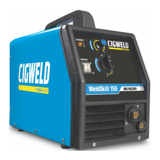
WeldSkill 100, 135, 150 MIG 4.03 WeldSkill 150 Mig Power Source Controls, Indicators and Features A. Wirespeed Control C. MIG Torch Connection (Euro) Fit the MIG Torch to the Power Source by pushing The Wirespeed Control knob controls the weld- the torch connector into the torch adaptor and ing current via the electrode wire feed rate which determines the speed of the wire feed motor. -
Page 44: Cigweld Mig Wire Selection Chart
WeldSkill 100, 135, 150 MIG 4.04 Cigweld MIG Wire Selection Chart Cigweld Welding Wire Selection Chart Application Description Diameter Pack Part Number WeldSkill Gasless 0.8mm Minispool 0.9kg WG0908 General purpose all positional wire ideal Mild Steel Wire for the home handyman. Applications 0.8mm Handispool 4.5kg WG4508... -
Page 45: Basic Welding Technique
WeldSkill 100, 135, 150 MIG 4.05 Basic Welding Technique Shielding Gas Nozzle (Optional) (Optional) Two different welding processes are covered in this Molten Metal section, with the intention of providing the very basic Flux Cored Molten Electrode concepts in using the Mig mode of welding, where a Slag Slag welding gun is hand held, and the electrode (welding... - Page 46 WeldSkill 100, 135, 150 MIG Travel Speed 5° to 15° The speed at which the molten pool travels influences Longitudinal Angle the width of the weld and penetration of the welding run. Direction of MIG Welding (GMAW) Varialbes 90° Travel Transverse Most of the welding done by all processes is on Angle...
- Page 47 WeldSkill 100, 135, 150 MIG 2. Wire Feed Speed. Increase in wire feed speed Establishing the Arc and Making Weld Beads increases weld current, Decrease in wire feed Before attempting to weld on a finished piece of work, speed decreases weld current. it is recommended that practice welds be made on a sample metal of the same material as that of the Gas Nozzle...
- Page 48 WeldSkill 100, 135, 150 MIG Electrode Wire Size Selection The choice of Electrode wire size and shielding gas used depends on the following • Thickness of the metal to be welded • Type of joint • Capacity of the wire feed unit and Power Source •...
-
Page 49: Service
WeldSkill 100, 135, 150 MIG SECTION 5: SERVICE 5.02 Cleaning the Welding Power 5.01 Routine Maintenance & Source Inspection WARNING WARNING Refer to WARNING on page 3-2. There are extremely dangerous voltage and power levels present inside this product. Do not attempt to open or repair unless To clean the Welding Power Source, open the you are a qualified electrical tradesperson. -
Page 50: Welding Problems
WeldSkill 100, 135, 150 MIG 5.05 Welding Problems Solving Problems Beyond the Welding Terminals. The general approach to fix Gas Metal Arc Welding (GMAW) problems is to start at the wire spool then work through to the MIG torch. There are two main areas where problems occur with GMAW, Porosity and Inconsistent wire feed Solving Problems Beyond the Welding Terminals - Porosity When there is a gas problem the result is usually porosity within the weld metal. - Page 51 WeldSkill 100, 135, 150 MIG Solving Problems Beyond the Welding Terminals - Inconsistent Wire Feed Wire feeding problems can be reduced by checking the following points. FAULT CAUSE 1 Wire spool brake is too tight Feed roller driven by motor in the cabinet will slip. 2 Wire spool brake is too loose Wire spool can unwind and tangle.
- Page 52 WeldSkill 100, 135, 150 MIG Welding Problems FAULT CAUSE REMEDY 1 Undercut A Welding arc voltage too A Reduce voltage by reducing the Output high. Voltage Control Switch positions or turn the Wirespeed control knob anticlockwise. B Incorrect torch angle B Adjust angle C Excessive heat input C Increase the torch travel speed or reduce...
-
Page 53: Power Source Problems
WeldSkill 100, 135, 150 MIG 8 Cold weld puddle A Faulty rectifier unit A Have an Accredited CIGWELD Service Provider test then replace the faulty component. B Loss of a phase in the B Check mains power Mains supply voltage. C Loose welding cable C Check all welding cable connections. - Page 54 WeldSkill 100, 135, 150 MIG Jerky wire feed A Worn or dirty contact tip A Replace B Worn feed roll. B Replace C Excessive back tension C Reduce brake tension on spool hub from wire reel hub. D Worn, kinked or dirty D Clean or replace conduit liner conduit liner No gas flow...
-
Page 55: Key Spare Parts
WeldSkill 100, 135, 150 MIG 5.07 Key Spare Parts CIGWELD PART NUMBER DESCRIPTION W4012900 Feed Roll 0.6/0.8mm, 100/135/150 Mig W4012901 Feed Roll 0.8/1.0mm, 100/135/150 Mig W4012902 Feed Roll 1.0/1.2mm, 100/135/150 Mig W4013000 Mig Torch, 100/135 Mig W4013100 Mig Torch, 150 Mig W7004600 PCB Assembly, 100/135/150 Mig W7004601... - Page 56 WeldSkill 100, 135, 150 MIG This Page Intentionally Blank SERVICE 0-5129...
-
Page 57: Appendix 1: 100 Mig Circuit Diagram
WeldSkill 100, 135, 150 MIG APPENDIX 1: 100 MIG CIRCUIT DIAGRAM 0-5129 APPEXDIX... -
Page 58: Appendix 2: 135 Mig Circuit Diagram
WeldSkill 100, 135, 150 MIG OPERATING MANUAL APPENDIX 2: 135 MIG CIRCUIT DIAGRAM Trigger Switch Appendix 0-5129... -
Page 59: Appendix 3: 150 Mig Circuit Diagram
WeldSkill 100, 135, 150 MIG APPENDIX 3: 150 MIG CIRCUIT DIAGRAM 0-5129 APPEXDIX... - Page 60 WeldSkill 100, 135, 150 MIG OPERATING MANUAL This page left blank intentionally. Appendix 0-5129...
-
Page 61: Cigweld - Limited Warranty Terms
CIGWELD - LIMITED WARRANTY TERMS LIMITED WARRANTY: CIGWELD Pty Ltd, An ESAB Brand, hereafter, “CIGWELD” warrants to customers of its authorized distributors hereafter “Purchaser” that its products will be free of defects in workmanship or material. Should any failure to conform to this warranty appear within the time period applicable to the CIGWELD products as stated below, CIGWELD shall, upon notification thereof and substantiation that the product has been stored, installed, operated, and maintained in accordance with CIGWELD’s specifications, instructions, recommendations and recognized... - Page 62 WeldSkill 100, 135, 150 MIG WARRANTY SCHEDULE – WELDSKILL 100, 135, 150 MIG WARRANTY WARRANTY PERIOD – (Parts and Labour) WeldSkill 100 Mig, WeldSkill 135 Mig and WeldSkill 150 1 Year Power Source ACCESSORIES WARRANTY PERIOD 3 Months Mig Torch and Work Lead Mig Torch Consumable Items Gas regulator/flowmeter (excluding seat assembly, pressure gauges, elastomer seals and "O"...
- Page 63 WeldSkill 100, 135, 150 MIG This Page Intentionally Blank...
- Page 64 CIGWELD Pty Ltd Singapore - Malaysia - Indonesia - CIGWELD An ESAB Brand ESAB Asia Pacific No 14 Jalan Teknologi 3/1 JI. Pulogadung No. 45 71 Gower Street, Preston VIC 3072 Australia 38 Joo Koon Circle Selangor Science Park 1...
Need help?
Do you have a question about the CIGWELD WeldSkill 100 MIG and is the answer not in the manual?
Questions and answers