Advertisement
Do you have a question about the Yoga Book 9i and is the answer not in the manual?
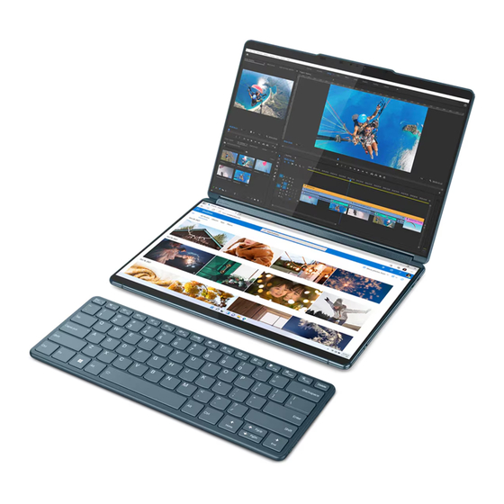
my external keyboard isnt working Yoga Book 9 13IRU8, doesnt seem to be charging, no light when i put it in pairing mode


Need help?
Do you have a question about the Yoga Book 9i and is the answer not in the manual?
Questions and answers
my external keyboard isnt working Yoga Book 9 13IRU8, doesnt seem to be charging, no light when i put it in pairing mode