Table of Contents
Advertisement
Quick Links
2008 Thermaltake Technology Co., Ltd. All Rights Reserved. 2008.08
C
All other registered trademarks belong to their respective companies.
Tested To Comply
With FCC Standards
FOR HOME OR OFFICE USE
Think Excitement - Think Spedo
www.thermaltake.com
Think Excitement - Think Spedo
User's Manual
Benutzerhandbuch
Mode d'emploi
Manual del usuario
Manuale dell'utente
安裝說明書
用戶手冊
ユーザーズマニュアル
Руководство пользователя
kullanıcı elkitabı
Series
Advertisement
Table of Contents

Related Manuals for Thermaltake Spedo Series


Summary of Contents for Thermaltake Spedo Series
- Page 1 Manuale dell’utente 安裝說明書 用戶手冊 ユーザーズマニュアル Руководство пользователя kullanıcı elkitabı 2008 Thermaltake Technology Co., Ltd. All Rights Reserved. 2008.08 All other registered trademarks belong to their respective companies. www.thermaltake.com Tested To Comply With FCC Standards FOR HOME OR OFFICE USE Think Excitement - Think Spedo...
-
Page 2: Specification
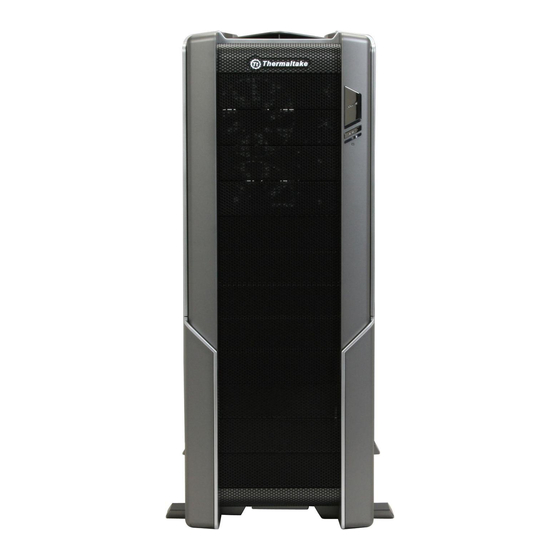
Specification Contents Chapter 1. Product Introduction Specification Chapter 2. Installation Guide Side Panel Disassembly VI90001W2Z VI90001N2Z Motherboard Installation Spedo Advance Package Spedo Model Name Power Supply Installation 5.25” Device Installation Case Type Full Tower 3.5” Device Installation Dimension (H*W*D) 536.0 x 232.0 x 610.0 mm / 21.1 x 9.1 x 24.0 inch HDD Installation Net Weight 13.0 kg / 28.7 lb... -
Page 3: Side Panel Disassembly
Left side panel Right side panel Side Panel Disassembly Motherboard Installation Left side panel disassembly Right side panel disassembly English / 1. Remove the I/O panel and lay down English / the case. Remove thumb screws on the back of the case, pull the handle to open the side panel. -
Page 4: Power Supply Installation
Power Supply Installation 5.25” Device Installation English / 1.Remove the front panel and 5.25” bay cover. English / 2.Push to release the 5.25” Place the power supply in proper location tool-free mechanism. and secure it with screws. 3.Slide the 5.25” device into the drive bay. - Page 5 3.5” Device Installation Italiano / 日本語 / 日本語 / 1.Rimuovere il pannello anteriore e il 1.前面パネルと5.25”ベイカバーを取り Adapter underside coperchio dell’alloggiamento da 5,25”. 外します。 2.Premere per rilasciare il meccanismo 2.5.25”の工具不要メカニズムを押して tool-free dell’alloggiamento da 5,25”. 解除します。 3.Fare scorrere il dispositivo da 5,25” 3.5.25”...
-
Page 6: Hdd Installation
Italiano / 日本語 / 日本語 / HDD Installation 1.Rimuovere il pannello anteriore e il 1.外付け3.5”デバイスを取り付ける coperchio a maglie da 5,25” ドライブベイから、前面パネルと5.25” dall’alloggiamento dell’unità se si メッシュカバーを取り外します。 desidera installare un dispositivo da 2.アダプタの金属製カバーを取り外し、 3,5” esterno. 外付け3.5”デバイスをねじでアダプタに 2.Rimuovere il coperchio di metallo 取り付けます。... - Page 7 Italiano / 日本語 / 日本語 / PCI Slot Tool-Free Usage 1.Rimuovere il vano dell’HDD premendo 1.工具不要メカニズムを押して HDD トレイを il meccanismo tool-free e tirare fuori il 取り外し、トレイを引っ張り出します。 vano. 2.ハードドライブを設置する前に、図に示すよう 2.Prima di posizionare il disco rigido, に4つのクリップが正しい位置になっているこ とを確認してください。 ハードドライブを assicurarsi che le quattro clip siano トレイの上に置き、クリップを押し返し、...
- Page 8 HDD Cage Swappable to 5.25” Drive Bay Italiano / 日本語 / 日本語 / 1.Rilasciare la clip in plastica come 1.図のようにプラスチック製のクリップ mostrato ed estrarre il supporto PCI. English / を外し、PCI ブラケットを取り除きます。 1.Release the HDD cage lock. 2.Posizionare il dispositivo PCI sulla 2.マザーボードに...
- Page 9 Italiano / 日本語 / 日本語 / Advanced Thermal Chamber Installation 1.Rilasciare il blocco del contenitore HDD. 1.HDD ケースロックを解除します。 ケースを Tirare il contenitore HDD e premere 引き出し、 ケースロックを押し返します。 l'apposito blocco HDD. 2.黒いコンバータを ケースの両側に取り付 2.Fissare il convertitore nero su entrambi けます。 i lati del contenitore HDD. 注意: コンバータの矢印は上を向いている必要があ...
- Page 10 Partition 1 Location Pin Italiano / 日本語 / 日本語 / 1.Sono presenti quattro partizioni, 1.4つの仕切りがあり、それぞれに番号が付 ciascuna delle quali numerata. いています。 2.La partizione deve essere inserita nel 2.仕切りは、ケースの対応する番号に挿入す numero corrispondente nel contenitore. る必要があります。 3.Il lato sinistro delle partizioni 1,2 e 4 English / 3.図に示すように、仕切り1、2、および4の...
- Page 11 Español / 2.隔板 3 左侧底部的定位销必须插入背面相应的 Partition 3 1.El pin de posición en la parte superior 位置。 izquierda de la partición 3 debe insertarse 3.其他定位销必须插入主板下方的安装孔。 en la última ranura de la ranura del PCI. 4.可根据缆线的位置调整隔板 3 上的可调挡板。 2.El pin de posición en la parte inferior izquierda de la partición 3 debe insertarse en la ubicación correspondiente en el lado 日本語...
- Page 12 Cable Routing Management Fanbar English / English / You can route excess cables Use the screws to secure the in the compartment between the 120mm fan to the fanbar. You motherboard and right side panel. can adjust the fanbar up and Secure the plastic covers to the down to support CPU or VGA’s corresponding insertions.
-
Page 13: Top Panel Disassembly
Top Panel Disassembly Leads Installation Guide English Leads Installation Guide Case LED connection / On the front of the case, you can find some LEDs and switch leads. Please consult your user manual of your motherboard manufacturer, then connect these leads to the panel header on the motherboard. USB 2.0 connection / Please consult your motherboard manual to find out the section of “USB connection”... - Page 14 Français Italiano Guide d'installation des fils Guida di installazione dei contatti Connexion des voyants du boîtier / Sur la face avant du boîtier, vous trouverez plusieurs voyants et les fils des Connessione del LED del case / Nella parte anteriore del case, sono presenti alcuni contatti per interruttori e LED. boutons.
- Page 15 Русский 简体中文 Указания по прокладке кабелей Указания по прокладке кабелей 线材安装说明 线材安装说明 Подключение индикаторов корпуса Подключение индикаторов корпуса / В передней части корпуса расположены индикаторы и провода 机壳LED连接方式 机壳LED连接方式 / 在机壳前方的面板后面,可以找到一些LED与开关线材(POWER Switch….),请参考主板 / 在机壳前方的面板后面,可以找到一些LED与开关线材(POWER Switch….),请参考主板 выключателей. Перед подсоединением этих проводов к монтажной колодке панели на материнской 使用说明书,并将机壳上的线材正确地连接到主板上,这些线材通常都会印有标签在上面,如果没有的话,请找...
- Page 16 4. Dedicated Graphic Card Power: reduce the loading on current PSU and no need to upgrade current PSU while running multi graphic cards mode. The functions can assure all Thermaltake Power Supply meets the balance in noise control and heat exhausted. All power supply provides complete protection function as follow: 1.
Need help?
Do you have a question about the Spedo Series and is the answer not in the manual?
Questions and answers