
Related Manuals for Thermaltake Shark


Summary of Contents for Thermaltake Shark
- Page 1 User's Manual User's Manual C 2004 Thermaltake Technology Co.,Ltd. All Rights Reserved. www.thermaltake.com...
-
Page 2: Table Of Contents
Contents Chapter1 Product Introduction 1.1 Specification 1.2 Features Chapter2 Case Mechanical Operation 2.1 How to open the side panel 2.2 Lock Operation 2.3 Installing 5.25" Device 2.4 Installing Internal 3.5" Device 2.5 Installing External 3.5" Device 2.6 PCI slot tool-free function operation 2.7 Motherboard Installation Chapter3 Motherboard &... -
Page 3: Chapter1 Product Introduction
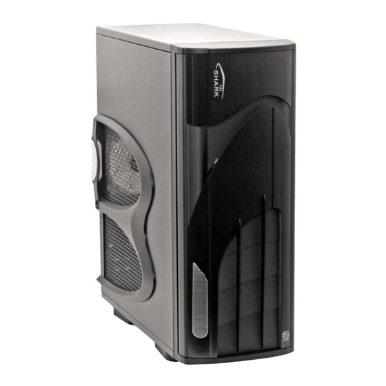
Chapter1 Product Introduction 1.2 Features 1.1 Specification Cooling System 12cm Dual cooling fans Best Ventilation: 12cm fans in front & rear Model Model VA7000SWA VA7000BWA Case Type Case Type Full Tower Full Tower Front View Side View Chassis overview Side Panel Side Panel Honeycomb See Honeycomb See... -
Page 4: Chapter2 Case Mechanical Operation
Chapter2 Case Mechanical Operation 2.2 Front door lock operation 2.1 How to open the side panel Locate the side panel key attached to the back side of the case. To unlock the side panel, turn the key clockwise shown in the picture. Insert the provided key and turn it clockwise. -
Page 5: Installing 5.25" Device
2.4 Installing 3.5" Device 2.3 Installing 5.25" Device Remove the front bezel by Remove the tray show in the picture by squeeze the clip grasping it at the bottom right corner and swinging on each side of the tray and outward. -
Page 6: Installing External 3.5" Device
2.6 PCI slot tool-free function operation 2.5 Installing 3.5" External Device Open the plastic clip then take off the PCI bracket as follow. u Squeeze tab and pull external 3.5" device cage out. Remove bezel. v Mount 3.5" device into the cage and fasten device in the case by screws. -
Page 7: Motherboard Installation
2.7 Motherboard Installation Chapter3 Leads connection 3.1 Case LED connections Unscrew the thumbscrews on the tray and remove it. On the front of the case, you can find some LEDs and switch leads (POWER SW*1, POWER LED*1, H.D.D. LED*1, RESET SW*1). Please consult user manual of your motherboard manufacturer, then connect these leads to the panel header on the motherboard. -
Page 8: Front I/O Pin Definition
3.2 Front I/O pin definition Chapter4 Other 4.1 Fits all Tt liquid Cooling system The pictures displaying below is for users to know that holes are made to the chassis for the installing of water-cooling system. It can be used for other brands of water-cooling system as well. User's Maunal... -
Page 9: Silent Purepower Power Supply (Optional)
AC Input cycled on/off under high temperature condition. Furthermore, it has been approved by UL, CSA, TUV, VDE, NODIC, CB, FCC, CE, CNS. There are three main products of Thermaltake PSU, it is divided into standard, VR and specialty power supply unit. Please refer to http://www.thermaltake.com/purepower/main.htm...
Need help?
Do you have a question about the Shark and is the answer not in the manual?
Questions and answers