Table of Contents
Advertisement
Quick Links
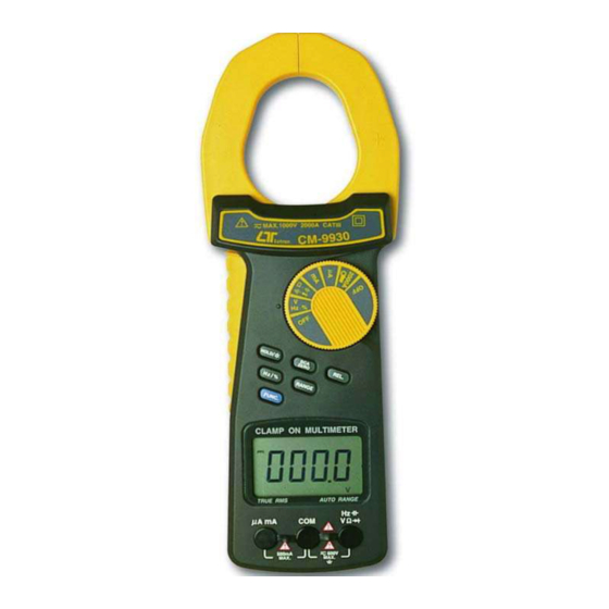
2000 A DCA/ACA CLAMP + DMM, true rms
DCA/ACA
CLAMP METER
Model : CM-9930
OPERATION MANUAL
Your purchase of this
DCA/ACA CLAMP METER
marks a step forward for
you into the field of
precision measurement.
Although
this
METER is a complex and
delicate instrument, its
durable
structure
allow many years of use
if
proper
operating
t e c h n i q u e s
developed. Please read
t h e
f o l l o w i n g
instructions
and always keep this
manual
within
reach.
CLAMP
will
a r e
carefully
easy
Advertisement
Table of Contents

Related Manuals for Tektronix CM-9930


Summary of Contents for Tektronix CM-9930
- Page 1 2000 A DCA/ACA CLAMP + DMM, true rms DCA/ACA CLAMP METER Model : CM-9930 Your purchase of this DCA/ACA CLAMP METER marks a step forward for you into the field of precision measurement. Although this CLAMP METER is a complex and...
- Page 2 Caution Symbol Caution : * Risk of electric shock ! Caution : * Do not apply the overload voltage, current to the input terminal ! * Remove test leads before open the battery cover ! * Cleaning - Only use the dry cloth to clean the plastic case ! Environment Conditions * Installation categories III .
-
Page 3: Table Of Contents
TABLE OF CONTENTS 1. FEATURES............... 1 2. SPECIFICATIONS.............1 2-1 General Specifications......... 1 2-2 Electrical Specifications........2 3. FRONT PANEL DESCRIPTION........4 4. PRECAUTIONS & PREPARATIONS FOR MEASUREMENT............5 5. MEASURING PROCEDURE......... 6 Symbols & Units of Display ..........DCV, ACV Measurement ..........Resistance Measurement.......... -
Page 4: Features
1. FEATURES * 2 in 1, 2000 A clamp meter + Digital multimeter. * Design meet IEC 1010 CATIII 1000V safety requirement. * True rms reading for ACV & ACA measurement. * 4000 counts, Auto range, multi-functions for ACA, DCA, ACV, DCV, Ohms, Capacitance, Hz, Duty cycle, diode and continuity check. -
Page 5: Electrical Specifications
Operating Temp. 0 to 50 to 122 ℃ ℃ ℉ ℉ Operating Less than 80% RH. Humidity Weight 380 g/0.85 LB (including battery). Dimension HWD : 255 x 73 x 38 mm. (10 x 2.9 x 1.5 inch) Max. Jaw 60 mm ( 2.36 inch ) Dia. - Page 6 Function Range Reso- Accuracy Overload lution Protection Ohms 400 ohm 0.1 ohm 4 K ohm 1 ohm ± ( 1 % + 5 d ) 40 K ohm 10 ohm 400 K ohm 100 ohm ± ( 2 % + 2 d ) 4 M ohm 1 K ohm AC / DC 400V...
-
Page 7: Front Panel Description
3. FRONT PANEL DESCRIPTION Fig. 1 Current Sense Jaws Function button ( DC/AC, ohm, Trigger Continuity, Diode Capacitance ) Function indicator 3-10 Manual range select button Function rotary switch 3-11 Display DCA zero button 3-12 uA/mA direct current input Relative button terminals Data hold / Back light 3-13... -
Page 8: Precautions & Preparations For Measurement
4. PRECAUTIONS & PREPARATIONS FOR MEASUREMENT 1) Ensure that the DC 9V battery is connected to its snap terminal with the right polarity and placed in the battery compartment correctly. 2) Place the Red & Black Test Leads into the proper input terminal before making measurement. -
Page 9: Measuring Procedure
5. MEASURING PROCEDURE 5-1 Symbols & units of display Symbols / Descriptions Units Appears when selecting DCV or DCA mode. Appears when selecting ACV & ACA mode. Appears when the " Data hold " function is operated. Appears when the " Relative " function is operated. -
Page 10: Dcv, Acv Measurement
5-2 DCV, ACV Measurement 1) Connect BLACK test lead into " COM " terminal. 2) Connect RED test lead into " V " terminal. 3) If measure " DCV ", select the " Function rotary switch " ( 3-4, Fig. 1 ) to the " V " position then push the "... -
Page 11: Diode Test
" " position then push the " FUNC. button " ( 3-9, Fig. 1 ) for display show " ". when the resistance value is less than 10 ohm, the beeper sound will be generated. 5-5 Diode Test 1) Connect BLACK test lead into " COM " terminal. 2) Connect RED test lead into "... -
Page 12: Ac Current Measurement ( Clamp On )
5-6 AC Current Measurement ( Clamp on ) 1) Select the " Function rotary switch " ( 3-4, Fig. 1 ) to the " 2000A " position then push the " FUNC. button " ( 3-9, Fig. 1 ) for display show " ". -
Page 13: Ac Current Measurement (Direct Input)
5-8 AC Current measurement (Direct input) 1) Connect BLACK test lead into " COM " terminal. 2) Connect RED test lead into " uA, mA " terminal. 3) If measure " uA " ( 400 uA, 4000 uA ), select the "... -
Page 14: Capacitance Measurement
5-10 Capacitance Measurement 1) Connect BLACK test lead into " COM " terminal. 2) Connect RED test lead into " " terminal. 3) Select the " Function rotary switch " ( 3-4, Fig. 1 ) to the " " position then push the " Function button " ( 3-9, Fig. -
Page 15: Duty Cycle Measurement
5-12 Duty Cycle Measurement All the measuring procedures are same as above 5-11 ( Frequency measurement ) except push the " Hz/% " ( 3-8, Fig. 1 ) for display show " % ". 5-13 Data Hold Operation 1) During the measurement, pushing the " Hold button " ( 3-7, Fig. -
Page 16: Maintenance
6. MAINTENANCE 6-1 Replacement of Battery Remove test leads before Caution : open the battery cover ! 1) When the LCD display shows " ". It is necessary to replace the battery, However in-spec. measurement may still be made for several hours after " Low battery indicator "... -
Page 17: Optional Accessories & Adapters
6-3 Cleaning Cleaning - Only use Caution : the dry cloth to clean the plastic case ! 7. OPTIONAL ACCESSORIES AND ADAPTERS Items Model Carry case CA-05A Humidity Adapter HA-702 Light Adapter LX-02 EMF Adapter EMF-824 Pressure Adapter PS-403 Anemometer Adapter AM-402 Tachometer Adapter TA-601 Sound Adapter... -
Page 18: The Address Of After Service Center
8. THE ADDRESS OF AFTER SERVICE CENTER 0711-CM9930...
Need help?
Do you have a question about the CM-9930 and is the answer not in the manual?
Questions and answers