
Related Manuals for ergoline ergoselect 1


Summary of Contents for ergoline ergoselect 1
- Page 1 1 Bicycle Ergometer Operator’s Manual 201000551000 • Version 2020-01-14 / Rev 01 • English...
- Page 3 1 Bicycle Ergometer Operator's Manual 201000551000 • Version 2020-01-14 / Rev 01 • English This manual was written with the utmost care. Should you still find details that do not corre‑ spond with the system, please let us know and we will correct the issue as soon as possible.
- Page 4 1...
-
Page 5: Table Of Contents
6.9.8 Pulse Display ........ergoselect 1... - Page 6 8.3 Family of characteristics of the braking torque control range ... Electromagnetic Compatibility EN 60601‑1‑2 ....ergoselect 1...
-
Page 7: General Information
1 General Information 1 General Information • The product ergoselect 1 bears the CE marking CE‑0123 • On request ergoline will provide a Field Service Manual. (Notified Body: TÜV), indicating its compliance with the provisions of the Council Directive 93/42/EEC about •... -
Page 8: Safety Information
• Patient Hazard, Equipment Damage • • Patient Hazard • Do not expose the ergoselect 1 to direct sunlight to prevent The German Medical Device Operator Ordinance (MPBetreibV, § 5) system components from reaching inadmissible high tempera- demands that users tures. -
Page 9: Contraindications
(Technical Specifications). • unstable angina with rest pain in the previous 48 hours • uncontrolled heart failure The ergoselect 1 ergometers may only be used in exercise • acute myocarditis or pericarditis testing and for rehabilitation of cardiac and cardiovas‑... -
Page 10: Intended Patient Group
If you have questions in this matter, please contact ergoline GmbH or an ergoline representative. 2.6 Applicable Laws, Regulations, and Directives If you have questions regarding laws, regulations or direc‑ tives related to the product, please contact ergoline GmbH. ergoselect 1... -
Page 11: Symbols
Nationally Recognized Testing Laboratory NRTL label for the USA and Canada. Do not lean against device: tipping hazard. Manufacturer’s identification. Date of manufacture. The number found under this symbol is the date of manufacture in the YYYY‑MM‑DD format. ergoselect 1... -
Page 12: Preparing The Patient
4 Preparing the Patient 4 Preparing the Patient 4.1 Adjusting Saddle and Handlebar The saddle height of the ergoselect 1 is adjusted manually with a clamping lever. When the pedal is in its lower position, there should be a 10° angle between the axis formed by the upper body and the thigh. -
Page 13: Setup And Mains Connection
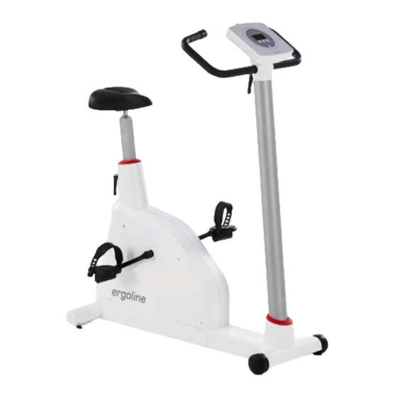
Leveling feet to adjust the ergometer to uneven floors Sockets for power cord and connection cables (underside of ergometer) Figure 5 – 1: Controls ergoselect 1 5.2 Mounting the Control Terminal The control terminal can be installed with the display either facing the patient or the operator. -
Page 14: Transport
5.4 Setup Place the ergoselect 1 on a level floor. The ergoselect 1 must be set up in a secure and stable position; the two leveling feet at the back make for easy adjustment to uneven floors. Extend the foot concerned until the ergoselect 1 no longer wobbles. -
Page 15: Connecting The Power Cord
• Tilt the ergometer carefully towards the front until it rests on the handlebar. Figure 5 – 5: Assembly position of the ergoselect 1 ergometer • Connect the power cord on the underside of the ergoselect 1. • Insert the power cord into the strain relief and screw the strain relief to the frame. -
Page 16: Connecting The Ecg Cable
5 Setup and Mains Connection 5.6 Connecting the ECG Cable The ergoselect 1 ergometers can be connected to electro‑ cardiographs and PC‑based ECG systems of most manufac‑ turers. The ergoselect 1 ergometers are equipped with a digital interface. The connection cable is plugged into the 9‑pole socket of Figure 5 –... -
Page 17: Operation
6 Operation 6 Operation Figure 6 – 1: ergoselect 1 control terminal 6.1 Turning the System On You turn on the ergometer by pressing the power switch. The ergometer runs a self‑test. Subsequently, the main menu displays. Figure 6 – 2: Self-test screen Note •... -
Page 18: Operating Modes
The functions of these three softkeys change with the displayed menu – the key label describing the function is shown on the display. Figure 6 – 4: ergoselect 1 – keypad and display 6.2 Operating Modes The ergoselect 1 ergometer supports the following operating modes: PC Mode An external device (e.g. -
Page 19: Pc Mode
(min) pedal speed (RPM) 6.5 Ergometry Use the softkeys on the right and left (↑ ↓) to position the bar cursor on Ergometry and confirm the selection with Select. Figure 6 – 9: Main menu ergoselect 1... -
Page 20: Terminating An Exercise Test
The load will immediately be reduced to 25 watts, but a higher or lower value can be selected manually. It is recommended that the patient continue to pedal in the recovery phase. The End key in the middle will terminate the test. Figure 6 – 13: Recovery phase ergoselect 1... -
Page 21: Manual
The exercise test can be terminated manually at any time with the End key located in the middle. The load will immediately drop to 0 watt. There is no recovery phase in the manual mode. Figure 6 – 16: Display during the exercise test ergoselect 1... -
Page 22: Settings
Use the softkeys on the right and left (↑ ↓) to position the bar cursor on the protocol to change (No. 6 to 15) and Figure 6 – 20: Selecting the exercise test protocol to edit confirm the selection with Select. ergoselect 1... -
Page 23: Contrast
Here you determine the increments for each load change. Depending on your choice, each key press will change the load by +/– 1, 5, 10 or 25 watts. Figure 6 – 24: Selecting the increment for manual load changes ergoselect 1... -
Page 24: Language
351 – 450 81 – 82 451 – 550 91 – 92 551 – 650 101 – 102 651 – 750 111 – 112 751 – 850 121 – 122 851 – 950 > 130 951 – 999 > 135 ergoselect 1... -
Page 25: Pulse Display
6 Operation 6.9.8 Pulse Display The pulse readout on the display can be turned off. Figure 6 – 28: Enable/disable the pulse readout ergoselect 1... -
Page 26: Cleaning, Maintenance, Disposal
B. Braun Melsungen AG: • Hexaquart plus ® (0.5 % / 5.0 %) • Hexaquart S ® (1.5 % / 5.0 %) • Meliseptol ® • Melsept SF ® (0.5 % / 5.0 %) ECOLAB: • Incidin Foam ® ergoselect 1... -
Page 27: Maintenance
The product described in this operator manual must not be disposed as unsorted municipal waste; it must be collected separately. Please contact your authorized manufacturer ergoline GmbH for information concerning the disposal of your equipment. There is no waste approval. Proper disposal is documented by ergoline GmbH. -
Page 28: Technical Specifications
8 Technical Specifications 8 Technical Specifications 8.1 Ergometer Model modular ergometer system model ergoselect 1 Operating mode continuous operation Power supply 100 – 240 V / 50 – 60 Hz / 100 VA max. Braking principle computer‑controlled eddy current brake Load range 6 –... -
Page 29: Exercise Test Protocols
3. Hollmann 4. STD France 5. Standard 6. – 15. (user programmable) Adjustment Range 20 – 100 1 – 30 1 – 400 20 – 100 (*) 1 – 99 (*) The recovery load is fixed at 25 W. ergoselect 1... -
Page 30: Family Of Characteristics Of The Braking Torque Control Range
8 Technical Specifications 8.3 Family of characteristics of the braking torque control range Figure 8 – 1: black: speed-independent range to DIN VDE 0750-0238 black + gray: speed-independent range of the ergoselect 1 ergometer ergoselect 1... -
Page 31: Electromagnetic Compatibility En 60601-1-2
Guidance and Manufacturer’s Declaration – Electromagnetic Emissions The ergoselect 1 ergometer is intended for use in the electromagnetic environment specified below. It is the responsi bility of the customer or user to ensure that the ergoselect 1 ergometer is used in such an environment. - Page 32 Guidance and Manufacturer’s Declaration – Electromagnetic Immunity The ergoselect 1 ergometer is intended for use in the electromagnetic environment specified below. It is the responsi bility of the customer or user to ensure that the ergoselect 1 ergometer is used in such an environment.
- Page 33 TV broadcast cannot be predicted theoretically with accuracy. To assess the electromagnetic environment due to fixed RF transmitters, an electromagnetic site survey should be considered. If the measured field strength in the location in which the ergoselect 1 ergo meter is used exceeds the applicable RF compliance level above, the ergoselect 1 ergometer should be observed to verify normal operation.
- Page 34 1 ergometer The ergoselect 1 ergometer is intended for use in an electromagnetic environment, as specified below, in which radiated RF disturbances are controlled. The customer or the user of the ergoselect 1 ergometer can help prevent electromagnetic inter‑...
- Page 36 GmbH Lindenstraße 5 72475 Bitz Germany Tel.: +49-(0) 7431 98 94 - 0 Fax: +49-(0) 7431 98 94 - 128 e-mail: info@ergoline.com http: www.ergoline.com...
Need help?
Do you have a question about the ergoselect 1 and is the answer not in the manual?
Questions and answers