Sign In
Upload
Download
Table of Contents
Contents
Add to my manuals
Delete from my manuals
Share
URL of this page:
HTML Link:
Bookmark this page
Add
Manual will be automatically added to "My Manuals"
Print this page
×
Bookmark added
×
Added to my manuals
Manuals
Brands
ACV Manuals
Boiler
SL320
Installation operation & maintenance
ACV Smart SL 320 Installation Operation & Maintenance
Hide thumbs
Also See for Smart SL 320
:
Product manual
(49 pages)
1
Table Of Contents
2
3
4
5
6
7
8
9
10
11
12
13
14
15
16
17
18
19
20
21
22
23
24
25
26
27
28
page
of
28
Go
/
28
Contents
Table of Contents
Bookmarks
Table of Contents
Table of Contents
General Recommendations
Energy Labelling
Rating Plate
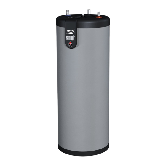
Appliance Description
Models - SL 320 - 420 - 420 Duplex - 600
Technical Characteristics
Dimensions and Main Characteristics
Electrical Characteristics
Performance
G3 Requirements and Guidance - UK Only
Installation
Safety Instructions
Packing Contents
Tools
Connection
Parallel Tank Assembly (Typical - 3 Tanks)
Connection Kits (Option)
Starting up
Safety Instructions to Fill the Tank
Filling
Checks before Starting up
Advertisement
Quick Links
Download this manual
Smart SL
320 - 420 - 420 Duplex - 600
Installation,
Operation &
Maintenance
Instructions for the User
and the Installer
A1007846 - 661Y3100 • C
Table of
Contents
Previous
Page
Next
Page
1
2
3
4
5
Advertisement
Table of Contents
Need help?
Do you have a question about the Smart SL 320 and is the answer not in the manual?
Ask a question
Questions and answers
Related Manuals for ACV Smart SL 320
Boiler ACV 2004 Product Manual
(49 pages)
Boiler ACV SMART Line SLE 130 Installation, Operating And Maintenance Instructions
(28 pages)
Boiler ACV SL420 Installation Operation & Maintenance
(28 pages)
Boiler ACV SLE 130 Installation, Operating And Servicing Instructions
(10 pages)
Boiler ACV SmartLine SLME Specification
(2 pages)
Boiler ACV Smart SL 100 Installation Operation & Maintenance
(40 pages)
Boiler ACV Smart line SLE W 100 Installation, Operating And Servicing Instruction
(16 pages)
Boiler ACV Smart SLEW 100 Installation Operation & Maintenance
(40 pages)
Boiler ACV Smart SLEW 130 Installation Operation & Maintenance
(40 pages)
Boiler ACV Smart SLEW 160 Installation Operation & Maintenance
(40 pages)
Boiler ACV Smart SLEW 210 Installation Operation & Maintenance
(40 pages)
Boiler ACV Smart SL 600 Installation Operation & Maintenance
(28 pages)
Boiler ACV Prestige 18 Manual
(12 pages)
Boiler ACV Prestige User's Information Manual
(40 pages)
Boiler ACV SMART 130 GREEN Installation, Operation And Maintenance Instructions
For the user and the installer (24 pages)
Boiler ACV Delta Pro S 25 Installation Operation & Maintenance
(33 pages)
This manual is also suitable for:
Smart sl 420
Smart sl 420 duplex
Smart sl 600
Table of Contents
Print
Rename the bookmark
Delete bookmark?
Delete from my manuals?
Login
Sign In
OR
Sign in with Facebook
Sign in with Google
Upload manual
Upload from disk
Upload from URL


Need help?
Do you have a question about the Smart SL 320 and is the answer not in the manual?
Questions and answers