CPI GRYPHON Technician Manual
Coin changer
Hide thumbs
Also See for GRYPHON:
- Operation and service manual (48 pages) ,
- Install manual (4 pages) ,
- User manual (223 pages)
Advertisement
Table of Contents
Gryphon™ coin changer
technician guide
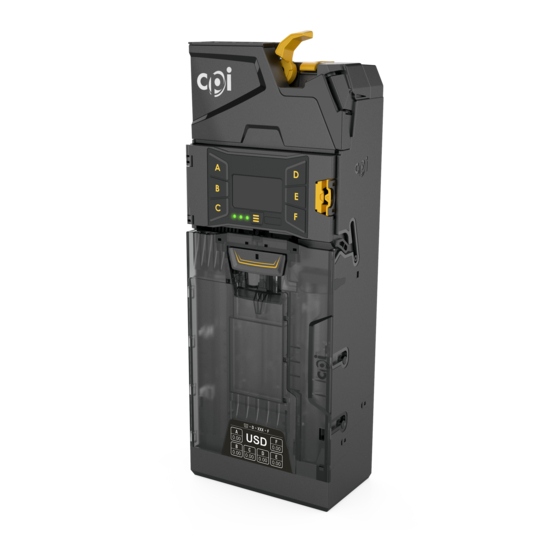
Components
Key coin changer components are identified below.
No.
Item
1
Coin return
2
Validator latch
Man machine
3
interface (MMI)
4
Diagnostic LEDs
5
Cassette
6
Dispenser
Cassette release
7
tab
8
Micro USB port
Keypad
The MMI screen displays messages related to current operational status and menu selections.
Always follow on-screen messages. See menu navigation tips below.
No.
Description
1
Display
Press keys A-F to navigate user menus. See
Keys A-F are also used to dispense coins from corresponding tubes
2
when in normal operating mode.
3
Move left
4
Move right
5
Scroll up
6
Scroll down
7
Previous page
8
Next page
Press to access
Press once to display previous menu.
9
Hold for 3 seconds to return to home screen.
10
Diagnostic
LEDs: red, amber, and green.
© 2023 Crane Payment Innovations. All rights reserved.
v1.0 EN
Description
Press to reject a coin and open the validator door.
Pull to remove the validator assembly.
Use this screen and keypad to interact with and
update the coin changer.
Displays the status of the coin changer with red,
amber, and green LEDs.
Stores coins for dispensing as change.
Dispenses coin returned as change.
Lift and pull to remove cassette from main housing.
Connect to a PC or USB memory stick for reading
audits, changing settings, and updating firmware.
Service
and
Setup
menus.
Symbols
for details.
support@cranepi.com
1
2
3
4
7
5
6
3
4
1
7
9
10
2
CPI support
8
5
6
8
1
Advertisement
Table of Contents

Related Manuals for CPI GRYPHON


Summary of Contents for CPI GRYPHON
- Page 1 Gryphon™ coin changer technician guide Components Key coin changer components are identified below. Item Description Coin return Press to reject a coin and open the validator door. Validator latch Pull to remove the validator assembly. Man machine Use this screen and keypad to interact with and interface (MMI) update the coin changer.
-
Page 2: Diagnostic Led
Menu navigation Unit is OK Unit requires attention Unit has fatal error. Replacement required. Unit is connected via USB to PC Unit is connected to USB stick Error support@cranepi.com CPI support © 2023 Crane Payment Innovations. All rights reserved. v1.0 EN... -
Page 3: Service Menu
Miscellaneous settings for items such as: currency for change accepted, display, and keypad • Error Log View and reset recent errors Test Run tests to confirm correct operation Language Change display language support@cranepi.com CPI support © 2023 Crane Payment Innovations. All rights reserved. v1.0 EN... -
Page 4: Installation
Fill the cassette with coins, ensuring coins are inserted into the proper tubes. Return the filled cassette to the coin changer and ensure it is correctly seated. Restore power to the vending machine. support@cranepi.com CPI support © 2023 Crane Payment Innovations. All rights reserved. v1.0 EN... - Page 5 50 mm (1.97 in) 46.5 mm (1.83 in) Maximum coin thickness = 3.5 mm (.14 in) Compliance Gryphon coin changer meets domestic and international standards for emission, safe product design, and environmental regulations. Contact your CPI service representative for details. support@cranepi.com CPI support ©...
Need help?
Do you have a question about the GRYPHON and is the answer not in the manual?
Questions and answers
Hello I just installed a brand new gryphon out of the box it displays no internal communication I installed a different one and it worked fine is there anything I can do to repair or it needs to go back I checked all connections and they seem perfect hook it up to my mdb tester and it it does not communicate to changer any help would be appreciated
If a CPI Gryphon displays no internal communication after installation, take the following troubleshooting steps:
1. Check connections:
- Ensure both ends of the MDB line are connected and powered.
- Verify the Synq cable is connected to the Synq port on the Gryphon.
2. If no Synq cable is pre-installed:
- Remove the PCB cover behind the acceptor module:
- Lift the yellow tab and pull the acceptor module forward.
- Press down on the tab to remove the PCB cover.
- Connect the Synq cable to the Synq port.
- Reattach the PCB cover and close the acceptor module.
3. Check device communication:
- For the bill validator, hopper, or recycler:
- Confirm they are connected correctly.
- If not responding, deactivate communication or replace if defective.
These steps help ensure all components are properly connected and communicating.
This answer is automatically generated