
Related Manuals for Ekinex EK-5IW-VI


Summary of Contents for Ekinex EK-5IW-VI
- Page 1 EK-5IW-VI Manuale d'uso Accessorio EK-5IW-VI Guida per l’installazione a incasso del videocitofono con riconoscimento facciale DICO EK-5DP-VI...
-
Page 2: Table Of Contents
EK-5IW-VI Sommario 1. Introduzione 2. Dispositivo DICO e accessori universali 3. Accessori per montaggio a incasso 4. Panoramica del prodotto 5. Ambiente di installazione 6. Installazione del dispositivo 7. Schema di cablaggio del dispositivo 8. Lunghezza del cavo e tabella AWG 9. -
Page 3: Introduzione
EK-5IW-VI 1. Introduzione Il dispositivo Ekinex EK-5DP-VI “DICO” è un videocitofono che offre un’eccellente co- municazione di tipo interfono e metodi di controllo degli accessi flessibili come il ricono- scimento facciale basato sull’intelligenza artificiale e controllabile dall’app mobile. L’in- stallazione del dispositivo può essere effettuata in uno dei seguenti modi, in alternativa: •... -
Page 4: Accessori Per Montaggio A Incasso
EK-5IW-VI 3. Accessori per montaggio a incasso Scatola per montag- Staffa da incasso x1 Placca per montaggio Vite con testa a croce gio a incasso x1 a incasso x1 M3x8 x7 Vite con testa a croce Tassello da muro in... -
Page 5: Panoramica Del Prodotto
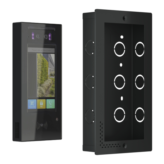
EK-5IW-VI 4. Panoramica del prodotto EK-5DP-VI FISPEK5IWVIIEXX00... -
Page 6: Ambiente Di Installazione
EK-5IW-VI Elemento LED a luce bianca Doppia telecamera LED infrarosso Microfono Schermo LCD Sensore fotosensibile Lettore card RF Altoparlante (laterale) 5. Ambiente di installazione Si prega di non posizionare il dispositivo sotto la luce diretta del sole, causerà effetti negativi o si romperà con l’alta temperatura. -
Page 7: Installazione Del Dispositivo
EK-5IW-VI 6. Installazione del dispositivo 6.1 Installazione della scatola per montaggio a incasso 1. Scavare nel muro un foro (altezza x 2. Posizionare la scatola da incasso larghezza x profondità = 225 x 111 x 43 nel foro e segnare sulla parete quattro mm) in base alla posizione del cavo. - Page 8 EK-5IW-VI Distanza 5. Eliminare i fori per i cavi della 6. Assicurarsi che il bordo superiore della scatola da incasso e far passare i cavi scatola da incasso non possa superare il attraverso il foro. Quindi fissare la filo muro e che rimanga spazio tra il fondo scatola con quattro viti testa a croce della scatola e il muro per lo scarico.
- Page 9 EK-5IW-VI 6.2 Installazione del videocitofono 1. Estrarre il dispositivo dalla confezione 2. Allineare i fori delle viti della staffa per montaggio a incasso con i fori sul retro del dispositivo (vedere l'immagine). Premere il gancio quadrato sul fondo della staffa contro la scanalatura sul fondo del dispositivo.
- Page 10 EK-5IW-VI 3. Allineare i montanti delle viti della staffa per montaggio a incasso con i fori delle viti della placca per montaggio a incasso. Quindi fissarli con quattro viti con testa a croce M3x8. 4. Far passare i cavi dalla scatola da incasso attraverso il foro quadrato sul coperchio...
- Page 11 EK-5IW-VI chiudere il coperchio del cablaggio. Quindi selezionare un tappo di gomma di dimensioni adeguate per spingere tutti i cavi nella copertura del cablaggio. Fissare la piastra pressa di tenuta al coperchio del cablaggio con due viti a esagono incassato M2.5x6.
- Page 12 EK-5IW-VI 6. Allineare i fori della placca con i fori della scatola da incasso (vedi figura), e utilizzare due viti a testa torx M4x16 per fissarle. 7. Verificare che la placca copra lo spazio intorno alla scatola da incasso. Accendere il dispositivo per verificare che il funzionamento sia corretto.
-
Page 13: Schema Di Cablaggio Del Dispositivo
EK-5IW-VI 7. Schema di cablaggio del dispositivo Alimentatore Ingresso 12 Vdc alim. Uscita Serratura relè Ingresso Porta Alimentatore 12 Vdc Attenzione! Quando si collega un disposi- tivo contenente una bobina, come un relè o una serratura elettromagnetica, è neces- sario proteggere il citofono dai picchi di... -
Page 14: Lunghezza Del Cavo E Tabella Awg
EK-5IW-VI 8. Lunghezza del cavo e tabella AWG Si prega di seguire il calibro/lunghezza del filo correttamente misurato per installare il dispositivo. 20 AWG 22 AWG 24 AWG 26 AWG Alimentatore ≤ 30m ≤ 20m ≤ 15m 12V 1,5A Alimentatore ≤... -
Page 15: Esempio Di Applicazione
EK-5IW-VI 10. Esempio di applicazione Ingresso Uscita Pulsante apertura Lettore card DICO FISPEK5IWVIIEXX00... -
Page 16: Configurazione
EK-5IW-VI 11. Configurazione Verifica dell'indirizzo IP: effettuare una pressione lunga in qualsiasi punto della schermata iniziale per circa cinque secondi per passare alla schermata di inserimento del System PIN; inserire il PIN predefinito "admin" e premere il pulsante Confirm per andare alla schermata delle impostazioni. In questa, premere l'icona Info per verificare l'indirizzo IP del dispositivo. -
Page 17: Avvertenze
Il codice sorgente del software sotto i termini di GNU GPL è gestito da Akuvox (Xiamen) Networks Co., Ltd e può essere scaricato online al seguente indirizzo: http://www.akuvox.com/gpl. © EKINEX S.p.A. 2023. La società si riserva il diritto di apportare modifiche alla presen- te documentazione senza preavviso. FISPEK5IWVIIEXX00... - Page 18 EK-5IW-VI www.ekinex.com Maggiori informazioni FISPEK5IWVIIEXX00...
- Page 19 EK-5IW-VI User Manual EK-5IW-VI accessory Guide for flush-mounting installation of the DICO EK-5DP-VI video intercom with facial recognition...
- Page 20 EK-5IW-VI Table of contents 1. Introduction 2. DICO device and universal accessories 3. Flush-mounting accessories 4. Product overview 5. Installation environment 6. Device installation 7. Device wiring 8. Cable length and AWG table 9. Application Network Topology 10. Application example 11.
-
Page 21: Introduction
EK-5IW-VI 1. Introduction The Ekinex EK-5DP-VI “DICO” device is a video intercom that offers excellent inter- com-type communication and flexible access control methods such as facial recognition based on artificial intelligence and controllable from the mobile app. The installation of the device can be done in one of the following alternative ways: •... -
Page 22: Flush-Mounting Accessories
EK-5IW-VI 3. Flush-mounting accessories Flush-mounting box Flush-mounting Flush-mounting board M3x8 crosshead bracket x1 screw x7 ST4x20 crosshead Tassello da muro in Vite torx M4x16 x2 Chiave torx x1 screw x4 plastica x4 FISPEK5IWVIIEXX00... -
Page 23: Product Overview
EK-5IW-VI 4. Product overview EK-5DP-VI FISPEK5IWVIIEXX00... -
Page 24: Installation Environment
EK-5IW-VI Element White light LED Camera Infrared LED Microphone Photosensitive sensor RF Card reader Loudspeaker (on the side) 5. Installation environment Please don't place the device under direct sunlight, it will bring bad effects or break under high temperature. If installing the device indoors, please keep the device at least 2 meters away from light and at least 3 meters away from windows and doors. -
Page 25: Device Installation
EK-5IW-VI 6. Device installation 6.1 Flush-mounting bracket installation 1. Dig out a square hole (height x width 2. Place the flush-mounting box in the x depth= 225 x 111 x 43 mm) according hole, and mark four positioning holes of to the position of cable. - Page 26 EK-5IW-VI Reserve a gap 5. Knock off the cable holes of the flush- 6. Please make sure that the top edge of mounting box, and lead cables through flush-mounting box can not over the wall, the hole. Then fix the box with four and need to reserve a gap between the ST4x20 crosshead screws on the wall.
- Page 27 EK-5IW-VI 6.2 Video intercom installation 1. Take the device out of the box 2. Align the screw holes of the flush-mounting bracket with holes on the back of the device (see the picture). And press up the square hook on the bottom of bracket against the groove on the bottom of the device.
- Page 28 EK-5IW-VI 3. Align the screw posts of the flush-mounting board with the screw holes of flush- mounting bracket. Then fix them with four M3x8 crosshead screws. 4. Lead the cables from the flush-mounting box through the square hole on the wiring...
- Page 29 EK-5IW-VI wiring cover. Then select a suitable size rubber plug to push all the cables into the wiring cover. Fix sealing pressing plate to the wiring cover with two M2.5x6 hex socket screws. Note: if the cables are less than 6, please use S size rubber plug; if the cables are more than 6 but less than 10, please use M size rubber plug;...
- Page 30 EK-5IW-VI 6. Align the holes of the flush-mounting board with the holes on the flush-mounting box (see the picture), and use two M4x16 torx head screws to fix them. 7. Check whether the flush-mounting board covers the gap around the flush-mounting box.
-
Page 31: Device Wiring
EK-5IW-VI 7. Device wiring 12 Vdc Power power supply input Relay Door lock output Exit input Warning! When a device containing a coil is connected, such as a relay or an electro- magnetic lock, it is necessary to protect the... -
Page 32: Cable Length And Awg Table
EK-5IW-VI 8. Cable length and AWG table Please follow the correctly measured wire gauge/length to install the device. 20 AWG 22 AWG 24 AWG 26 AWG 12V 1,5A ≤ 30m ≤ 20m ≤ 15m power supply 12V 1A ≤ 20m ≤... -
Page 33: Application Example
EK-5IW-VI 10. Application example Input Output Exit button Card reader DICO FISPEK5IWVIIEXX00... -
Page 34: Configuration
EK-5IW-VI 11. Configuration IP address checking: long press anywhere on the home screen for about five seconds to go to the System PIN entry screen; enter the default PIN "admin" and press Confirm button to go to the setting screen. In this, press the Info icon to check the IP address of the device. -
Page 35: Warning
The source code of the software under the terms of the GNU GPL is maintained by Akuvox (Xiamen) Networks Co., Ltd and can be downloaded online at the following address: http://www.akuvox.com/gpl. © EKINEX S.p.A. 2023. The company reserves the right to make changes to this docu- mentation without notice. FISPEK5IWVIIEXX00... - Page 36 EK-5IW-VI www.ekinex.com More info FISPEK5IWVIIEXX00...
Need help?
Do you have a question about the EK-5IW-VI and is the answer not in the manual?
Questions and answers