Table of Contents
Advertisement
Quick Links
Advertisement
Table of Contents

Related Manuals for Veolia Sievers TOC-R3


Summary of Contents for Veolia Sievers TOC-R3
- Page 2 Access the Sievers* website [Customer Support > Sievers Analyzers & Instruments] An electronic version of the Analyzer’s Operation and Maintenance Manual is accessible from the Sievers website: [Customer Support > Sievers Analyzers & Instruments]. * Trademark of Veolia; may be registered in one or more countries.
-
Page 3: Identification Records
Identification Records Analyzer Serial Number: _________ (This is located on the side of the Analyzer.) Default Machine PIN: 1111 Default Superuser Password: 1234 Sievers TOC-R3 Operation and Maintenance Manual DLM 95000-01 EN Rev. A © Veolia 2023... - Page 4 AGE IS NTENTIONALLY LANK Sievers TOC-R3 Operation and Maintenance Manual DLM 95000-01 EN Rev. A © Veolia 2023...
-
Page 5: Table Of Contents
Optional Subsystems and Hardware ........36 Sievers TOC-R3 Operation and Maintenance Manual DLM 95000-01 EN Rev. - Page 6 Air Scrubber ............53 Sievers TOC-R3 Operation and Maintenance Manual DLM 95000-01 EN Rev.
- Page 7 Connecting the Analyzer to a Sample Point ......76 Installing the Particulate Sampler, Optional ......76 Sievers TOC-R3 Operation and Maintenance Manual DLM 95000-01 EN Rev.
- Page 8 Test the Relay(s) (Binary Output)....... . . 95 Sievers TOC-R3 Operation and Maintenance Manual DLM 95000-01 EN Rev.
- Page 9 Fan Filter ............116 Sievers TOC-R3 Operation and Maintenance Manual DLM 95000-01 EN Rev.
- Page 10 Auto Lock Duration..........157 Sievers TOC-R3 Operation and Maintenance Manual DLM 95000-01 EN Rev.
- Page 11 To Inspect and Clean the Analyzer Exterior ......183 To Inspect and Clean the Analyzer Interior ......183 Sievers TOC-R3 Operation and Maintenance Manual DLM 95000-01 EN Rev.
- Page 12 To Access the Furnace Foot Assembly ......210 To Inspect the Bottom of the Furnace Cartridge ....211 Sievers TOC-R3 Operation and Maintenance Manual DLM 95000-01 EN Rev.
- Page 13 Particulate Sampler Dimensions ........234 Sievers TOC-R3 Operation and Maintenance Manual DLM 95000-01 EN Rev.
- Page 14 Index ..............284 Sievers TOC-R3 Operation and Maintenance Manual DLM 95000-01 EN Rev.
-
Page 15: List Of Tables
Table C-2: Modbus Register Table ..........266 Sievers TOC-R3 Operation and Maintenance Manual DLM 95000-01 EN Rev. -
Page 16: List Of Figures
Figure 4-20: Injection Timing VS Integration ........123 Sievers TOC-R3 Operation and Maintenance Manual DLM 95000-01 EN Rev. - Page 17 Figure 6-5: MFSV Vent Absorber Cartridge ........191 Sievers TOC-R3 Operation and Maintenance Manual DLM 95000-01 EN Rev.
- Page 18 Figure A-21: Gas Cooler Unit (EC1), View from Above ......249 Sievers TOC-R3 Operation and Maintenance Manual DLM 95000-01 EN Rev.
-
Page 19: Revision History
First publication, Firmware version 1.16 or later Apr 2023 RADEMARKS AND ATENTS Sievers* is a trademark of Veolia and may be registered in one or more countries. ® ® Viton is a registered trademark of The Chemours Company FC, LLC. Scotch-Brite is a ®... - Page 20 Customers shall pay freight charges, including all taxes and duties, for all products returning to Veolia. Any product returned to the factory without an RA number will be returned to the customer.
- Page 21 Operation and Maintenance Manual is believed to be accurate at the time of publication and no responsibility is taken for any errors that may be present. In no event shall Veolia be liable for incidental or consequential damages in connection with or arising from the use of the manual and its accompanying related materials.
- Page 22 être engagée pour les éventuelles erreurs qu’il pourrait contenir. Le groupe Veolia ne saurait en aucun cas être tenu pour responsable des préjudices accidentels ou de quelque nature que ce soit, dus à l’utilisation du manuel ou de la documentation connexe.
- Page 23 を、Veolia の書面による同意なしに、最初の購入者から第三者に譲渡することはできませ ん。 Veolia は、商品性および特定の目的に対する適合性の黙示の保証を一切拒否します。 赔偿与责任限制 上述保证不适 户不正确或不恰当的安装、维护、调整、校准或操作导致的故障。安 用于因客 装、维护、调整、校准或操作必须遵循操作与维护手册中的说明进行。使用非推荐的维护材 料可能会导致保证失效。 这里提供的赔偿为客户的唯一和独占赔偿。在任何情况下,Veolia 不对任何直接的、间接 的、特殊的、偶发的或连带发生的损失 (包括利润损失)负责,无论这些损害是依据何种合同 责任理论、侵权行为责任理论或其它法律理论进行推断的。操作与维护手册在出版时被认为是 准确的,Veolia 不对其中可能存在的任何错误负责。在任何情况下,Veolia 均不对因使用该 手册 (或与其使用有关)或相关材料导致的偶发或连带发生的损失负责。保证仅对原购买者有 效。未经 Veolia 明确书面同意,此有限保证不可由原购买者转让给任何其他方。Veolia 特此声 明不提供任何关于特殊用途的适销性和适用性的暗示担保。 Sievers TOC-R3 Operation and Maintenance Manual DLM 95000-01 EN Rev. A © Veolia 2023...
-
Page 24: Warnings
Analyzer, including installation of maintenance items, could result in injury. If this instrument is used in a manner not specified by Veolia, the protection provided by the instrument may be impaired. Use a 2-person lift. This instrument weighs over 18 kg (40 lb). It is the policy of OSHA and Veolia to require a 2-person lift for items weighing over 18 kg (40 lb). - Page 25 Ensure that the power switch on the side of the Analyzer is OFF before connecting to a power supply. Sievers TOC-R3 Operation and Maintenance Manual DLM 95000-01 EN Rev. A © Veolia 2023...
- Page 26 NATIONAL ELECTRICAL CODE, ANSI/NFPA NO. 70. Use of the supplied AC power cord will ensure safe operation of the Analyzer. Use of a power cord not supplied by Veolia is not authorized and may impair the safety of the equipment.
- Page 27 To protect the Analyzer from damage, always drain the fluids from the Analyzer prior to shipping. This symbol on the instrument indicates that the product is China RoHS II compliant. Sievers TOC-R3 Operation and Maintenance Manual DLM 95000-01 EN Rev. A © Veolia 2023...
-
Page 28: Chapter 1: Introduction
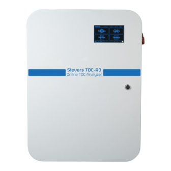
The Sievers TOC-R3 Online TOC Analyzer (henceforth referred to as Sievers TOC-R3) from Veolia is an industrial robust Analyzer used to measure the concentration of Total Carbon (TC), Total Inorganic Carbon (TIC), Total Organic Carbon (TOC), and Non-Purgeable Organic Carbon (NPOC) in water samples. - Page 29 ... . Chapter 1 NT ROD UCTI ON AGE IS NTENTIONALLY LANK Sievers TOC-R3 Operation and Maintenance Manual DLM 95000-01 EN Rev. A © Veolia 2023...
-
Page 30: Chapter 2: System Description
†Stated analytical performance achieved under ideal laboratory conditions using 0-10 mg/L NDIR Detector. * Requires the purchase of an Optional Detector; either PID Detector (for POC/VOC) or ECD Detector (for TNb). The Analyzer cannot be configured with both purchasable Detectors. Sievers TOC-R3 Operation and Maintenance Manual DLM 95000-01 EN Rev. A... -
Page 31: Important
• Repeatability: ± 2 % End Of Detector Range • Salt Tolerance: 3-5% NaCl • Typical Cycle Time: TC ~ 1 min, NPOC ~ 3 min Sievers TOC-R3 Operation and Maintenance Manual DLM 95000-01 EN Rev. A © Veolia 2023... -
Page 32: Additional System And Operating Specifications
Acid Selection and Concentration is based on the sample and Analytical Method used. 1. Typical Sample Time is Sample and Analytical Method dependent. 2. The Analyzer cannot be configured with both optional Detectors. Sievers TOC-R3 Operation and Maintenance Manual DLM 95000-01 EN Rev. A © Veolia 2023... -
Page 33: Dilution And Rinsing Water
TC ~ 1 min, NPOC ~ 3 min These specifications are unique and dependent on each customer environment. 3. Typical Sample Time is Sample and Analytical Method dependent. Sievers TOC-R3 Operation and Maintenance Manual DLM 95000-01 EN Rev. A © Veolia 2023... -
Page 34: Communication
These specifications are unique and dependent on each customer sample stream. Monthly Dilution Water: These specifications are unique and dependent on each customer sample stream. No Catalyst Required Sievers TOC-R3 Operation and Maintenance Manual DLM 95000-01 EN Rev. A © Veolia 2023... -
Page 35: Compliance
Enclosure Specific Manual. Major Subsystems The Sievers TOC-R3 consists of four Major Subsystems. The modules are designed as separate compartments within the enclosure to prevent contamination. The touch panel PC (referred to as “Touchscreen”) is mounted on the front panel and is accessible from the outside of the Analyzer. -
Page 36: Optional Subsystems And Hardware
“CM2 — Multi-Function Sample Vessel” on page 46 Figure 2-2 on page Optional Subsystems and Hardware The Sievers TOC-R3 has six Optional Subsystems, depending on optional hardware purchased. 1. Communication Box — Optional solution for Input/Output Analyzer signals. See “Data Inputs / Outputs”... -
Page 37: Theory Of Operation
NPOC can then be further classified as Dissolved Organic Carbon (DOC) and colloids/particulates. DOC is only that amount filtered through 0.45 µm. However both suspended and dissolved organics can impact water treatment efficiency. Sievers TOC-R3 Operation and Maintenance Manual DLM 95000-01 EN Rev. A... -
Page 38: Total Nitrogen (Tnb) Parameter
NDIR Detector. Included Standard Operation Analytical Methods The TC Method and NPOC Method are provided as a standard operation Analytical Methods. Sievers TOC-R3 Operation and Maintenance Manual DLM 95000-01 EN Rev. A © Veolia 2023... -
Page 39: Tc Method
CO As before, the carbon dioxide is measured in the NDIR Detector, and the TIC concentration is calculated. This Method is not oxidized but instead sent straight to the Sievers TOC-R3 Operation and Maintenance Manual DLM 95000-01 EN Rev. A... -
Page 40: Toc Diff Method (Toc)
Nitrogen components to form NO. The area integral of the NO detection peak corresponds to the TNb content. The measurement of TNb is of Sievers TOC-R3 Operation and Maintenance Manual DLM 95000-01 EN Rev. A... -
Page 41: Sample Flow Path
This Method is a purchasable option. AMPLE The Sievers TOC-R3 is available in two primary configurations: Single-Stream or Two-Stream configurations. The optional Two-Stream configuration has up to two Sample Inlets. For more information, see... -
Page 42: Flow Path Components
For more information, please contact Sievers Technical Support or your Local Service Provider. The "raw" NDIR Detector signals are displayed as “CO in ppm” and the concentrations are displayed in “mg/L”. Sievers TOC-R3 Operation and Maintenance Manual DLM 95000-01 EN Rev. A © Veolia 2023... -
Page 43: B2 - Ecd Detector Option (For No Detection)
This is determined during product planning and custom installed individually per Customer requirements. 4. “B2” can either be the optional ECD Detector or the optional PID Detector. The Analyzer cannot be configured with both options. Sievers TOC-R3 Operation and Maintenance Manual DLM 95000-01 EN Rev. A © Veolia 2023... -
Page 44: B2 - Pid Detector Option (For Poc/Voc Detection)
POCs/VOCs are stripped out of solution depends on many factors including 5. “B2” can either be the optional PID Detector or the optional ECD Detector. The Analyzer cannot be configured with both options. Sievers TOC-R3 Operation and Maintenance Manual DLM 95000-01 EN Rev. A... -
Page 45: Sensors
Carrier Gas used to inject sample into the Furnace. The CM1 uses the system inlet regulated pressure (the “Carrier Gas Flow In” pressure setting). The “Carrier Gas Flow In” setting should never exceed 35 l/h. Sievers TOC-R3 Operation and Maintenance Manual DLM 95000-01 EN Rev. A... -
Page 46: Cm2 - Multi-Function Sample Vessel
The GP1 Pump Tubing is replaced as part of regular maintenance. This pump has both clockwise direction (CW) and anticlockwise (ACW) pumping. 6. Service level access requires Certified Sievers Technician or next level support. Sievers TOC-R3 Operation and Maintenance Manual DLM 95000-01 EN Rev. A... -
Page 47: Filters
Carrier Gas option selected by the Customer, this will either be in the form of an external pressure regulator provided by the Customer (if using Nitrogen or compressed air) or the Regulator located inside the Air Box enclosure, if using the Optional Air Box Accessory. Sievers TOC-R3 Operation and Maintenance Manual DLM 95000-01 EN Rev. A... -
Page 48: Mfsv Vent
This valve controls Sample Inlet Calibration/Grab Valve This valve controls the Calibration/Grab Sample Inlet. MFSV Valve This valve controls the loading of the MFSV and Injection Loop. Sievers TOC-R3 Operation and Maintenance Manual DLM 95000-01 EN Rev. A © Veolia 2023... -
Page 49: Wetted Materials
Use this table to learn about the Wetted Materials within the Analyzer. This list represents the components that sample interacts with within the Analyzer. Table 2-5: Wetted Materials List Module Part Material Sample Inlet(s) Tube PTFE Sievers TOC-R3 Operation and Maintenance Manual DLM 95000-01 EN Rev. A © Veolia 2023... - Page 50 PTFE Seal Crew Connection PTFE Tube Air Viton® / FKM Condensate Pump (GP2) Tube Viton® / FKM Y-Connector Tube - Pump Marprene® a. And internal contents. Sievers TOC-R3 Operation and Maintenance Manual DLM 95000-01 EN Rev. A © Veolia 2023...
-
Page 51: Additional System Components
Analyzer. Data Inputs / Outputs The Sievers TOC-R3 offers four isolated Digital Inputs (Binary), four isolated Digital Binary Outputs (referred to as “Relays”), and six isolated Analog Outputs (0/4-20 mA). The Analyzer also includes one USB 2.0 Port and one Gigabit Ethernet Port output allowing flexibility for exporting data, such as Backup Settings, Machine Report, and taking screenshots. -
Page 52: Ethernet
For information on how to configure the 0/4-20 mA, Analog Outputs, refer to “Analog Output” on page 139. Sievers TOC-R3 Operation and Maintenance Manual DLM 95000-01 EN Rev. A © Veolia 2023... -
Page 53: Options And Accessories
Indicator. This size provides a large surface area for the reaction of CO with the Soda Lime, leading to efficient removal of CO from the air. If using Soda Lime with Sievers TOC-R3 Operation and Maintenance Manual DLM 95000-01 EN Rev. A © Veolia 2023... -
Page 54: Activated Carbon
The Mounting Rack is a supplemental option to support the installation and setup of the Analyzer. For more information, consult the documentation delivered with the accessory. See also, “Mounting Rack Dimensions” on page 235. Sievers TOC-R3 Operation and Maintenance Manual DLM 95000-01 EN Rev. A © Veolia 2023... - Page 55 ... . Chapter 2 YS TEM ESCR IPTION AGE IS NTENTIONALLY LANK Sievers TOC-R3 Operation and Maintenance Manual DLM 95000-01 EN Rev. A © Veolia 2023...
-
Page 56: Chapter 3: Installation
......... VERVIEW This chapter provides installation instructions for the Sievers TOC-R3. For additional assistance, contact Technical Support or your local service provider. Startup and Analyzer familiarization training by a qualified service technician is also available for purchase. -
Page 57: Sample Considerations
Analyzer location. • Options: Nitrogen, Zero/Synthetic Air, Plant Instrument Air (ANSI 7.0.01), or Air Box Accessory. • Pressure: 100-200 kPa (1-2 Bar, 14.5-29 psig) Sievers TOC-R3 Operation and Maintenance Manual DLM 95000-01 EN Rev. A © Veolia 2023... -
Page 58: Acid
The Analyzer requires deionized water (DI Water, low TOC < 1 ppm) for Dilution and Rinsing, if using. The Carboy and Dilution/Rinse Water are both User provided. User Requirements To install the Sievers TOC-R3, the following User-supplied equipment is required: • ESD (Electrostatic Discharge) Grounding Strap •... -
Page 59: Step 1: Unpack And Inspect The Analyzer
There is a charge for new packaging materials to return the Analyzer. Sievers TOC-R3 Operation and Maintenance Manual DLM 95000-01 EN Rev. A © Veolia 2023... -
Page 60: Figure 3-1: Remove Shipping Kit And Internal Shipping Materials
Inspect the Analyzer for any damage. If damage has occurred during shipment, contact Technical Support or your local service provider. Figure 3-1: Remove Shipping Kit and Internal Shipping Materials Figure 3-2: Optional Accessory Shipping Material Sievers TOC-R3 Operation and Maintenance Manual DLM 95000-01 EN Rev. A © Veolia 2023... -
Page 61: Shipping List
... . Chapter 3 NS TAL LAT ION Shipping List: • Sievers TOC-R3 • Installation Guide • Operation and Maintenance Manual (accessed from the Sievers website). ► For more information, see page •... - Page 62 (This hardware comes pre-installed on the Furnace Head Cover [6]) Furnace Head O-Ring Furnace Foot Assembly* Furnace Foot Z-Bracket (Curved edge) Injection Block Compression Fitting Injection Needle* Ceramic Disk* Sievers TOC-R3 Operation and Maintenance Manual DLM 95000-01 EN Rev. A © Veolia 2023...
- Page 63 Waste Tube; PVC (OD 14 mm, ID 10 Air Box Air Scrubber (Comes with two mounting brackets) Arrives pre-filled with Activated Carbon Filter Cartridge. Communication Box Particulate Sampler Sievers TOC-R3 Operation and Maintenance Manual DLM 95000-01 EN Rev. A © Veolia 2023...
-
Page 64: Step 2: Select A Location For The Analyzer
Analyzer interior. Analyzer Dimensions: Weight: Height: 900 mm (35.5 in) 55 kg (121 lb) Width: 644.3mm (25.4 in) Use a 2-person lift! Depth: 354.5 mm (14 in) Sievers TOC-R3 Operation and Maintenance Manual DLM 95000-01 EN Rev. A © Veolia 2023... -
Page 65: Table 3-2: Connections/Ports List
Connection/ Port Name Port Number Enclosure Drain Sample Waste Outlet (Gravity Drain) Dilution / Rinsing Water Acid Supply Inlet Calibration, Single Measurement, and Check Standard Inlet Sievers TOC-R3 Operation and Maintenance Manual DLM 95000-01 EN Rev. A © Veolia 2023... -
Page 66: Nstall Any Optional I/Oor Carrier
After installing the Air Box and Air Scrubber, if using, connect the Communication Box wire connections to the Analyzer. Ensure the Air Box power wiring connections have been completed prior to connecting the Communication Box wiring to the Analyzer. Sievers TOC-R3 Operation and Maintenance Manual DLM 95000-01 EN Rev. A... -
Page 67: Communication Box
A standard should be chosen that fits the Method(s) and placed below the Analyzer with the Calibration Line inserted into the carboy. (If the measurement is running, Sievers TOC-R3 Operation and Maintenance Manual DLM 95000-01 EN Rev. A... -
Page 68: Table 3-3: Communication Box I/O Terminal Block Pin Details
Digital Input 2 Isolated Binary Input 2 (DI13) Monitor: Stream 2 Digital Input 3 Isolated Binary Input 3 (DI14) Check 7. Future function. May not be configurable. Sievers TOC-R3 Operation and Maintenance Manual DLM 95000-01 EN Rev. A © Veolia 2023... -
Page 69: Figure 3-4: Communication Box Terminal Block And Power Rail Connections
Figure 3-4: Communication Box Terminal Block and Power Rail Connections If using the Air Box Accessory, continue to the next procedure. If not, continue to “Communication Box Wire Connection” on page Sievers TOC-R3 Operation and Maintenance Manual DLM 95000-01 EN Rev. A... -
Page 70: Air Box
Scrubber Housing must first be filled with Soda Lime before connecting it to the Analyzer. Install the provided Mounting Brackets near the Analyzer either on a wall or rack. The Air Sievers TOC-R3 Operation and Maintenance Manual DLM 95000-01 EN Rev. A... -
Page 71: Prepare The Air Scrubber Housing
8. The Activated Carbon Filter Cartridge is only intended for initial installation configuration. When performing maintenance later, it will be replaced with Activated Carbon loose granules (User provided) instead of a cartridge. Sievers TOC-R3 Operation and Maintenance Manual DLM 95000-01 EN Rev. A... -
Page 72: Communication Box Wire Connection
Connect the Nitrogen source Carrier Gas Tubing to the Analyzer Carrier Gas Inlet (Port If Using Zero/Synthetic Air: Connect the Zero/Synthetic Air source Carrier Gas Tubing to the Analyzer Carrier Gas Inlet (Port 9). Sievers TOC-R3 Operation and Maintenance Manual DLM 95000-01 EN Rev. A © Veolia 2023... -
Page 73: If Using Plant Instrument Air (Ansi/Isa 7.0.01)
6. Using the other section of Carrier Gas Tubing, connect the Air Scrubber Outlet (off- center port on top of Air Scrubber Housing) to the Analyzer Carrier Gas Inlet (Port 9). Sievers TOC-R3 Operation and Maintenance Manual DLM 95000-01 EN Rev. A... -
Page 74: Step 5: Connect The Waste Line
Figure 3-7 on page 5. Route the other end of the Waste Tubing [18] into a free-flowing, ventilated gravity drain below the Analyzer. Ensure the tubing is and will not be submerged. Sievers TOC-R3 Operation and Maintenance Manual DLM 95000-01 EN Rev. A... -
Page 75: Figure 3-7: Connect The Waste Tubing [18]
C. Release the valve plunger once the Pinch/Drain Tubing has been installed. This closes the Y9 Pinch Valve and pinches the MFSV Drain tubing shut. See Figure 3-8 on page Sievers TOC-R3 Operation and Maintenance Manual DLM 95000-01 EN Rev. A... -
Page 76: Connecting The Analyzer To A Sample Point
Installing the Particulate Sampler, Optional NOTE: This accessory uses Metric Standard connections. The Inlet and Outlet are Slip/Slip (Female) Fittings for DIN 32 Schedule 40 PVC. Sievers TOC-R3 Operation and Maintenance Manual DLM 95000-01 EN Rev. A © Veolia 2023... -
Page 77: Step 7: Install The Acid
Acid Pump. Connect the other, shorter Acid line to the Outlet, off-center port on the Acid Pump. Ensure the tubing is tightly secured by gently pulling back on it. Figure 3-9 on page Sievers TOC-R3 Operation and Maintenance Manual DLM 95000-01 EN Rev. A © Veolia 2023... -
Page 78: Prepare The Acid
Water Line (Port 3) comes pre-installed from the factory. Place the loose end of the Dilution/ Rinse Water Tubing into the prepared carboy. Ensure the tubing reaches the bottom of the carboy. The tubing length can be adjusted or cut, if needed. Sievers TOC-R3 Operation and Maintenance Manual DLM 95000-01 EN Rev. A... -
Page 79: Step 9: Prepare The Furnace
Figure 3-10 on page 3. From the top left corner of the Furnace, disconnect the Wing Screw securing the Furnace in its upright position. Do not lose this hardware! Sievers TOC-R3 Operation and Maintenance Manual DLM 95000-01 EN Rev. A... -
Page 80: Prepare The Furnace
Furnace using the three Thumb Screws [17]. These brackets will be tightened in a later step. Attach them to the Furnace but keep them loose. See Figure 3-12 on page Sievers TOC-R3 Operation and Maintenance Manual DLM 95000-01 EN Rev. A © Veolia 2023... -
Page 81: Prepare And Install The Furnace Cartridge
3. Insert the Injection Needle [15] through the loosened Compression [10A] and Furnace Head Cover [6]. NOTE: If needed, you can remove the Furnace Head Compression Fitting [10] and individually slide the Nut and Ferrules [10A through 10D] on to the Sievers TOC-R3 Operation and Maintenance Manual DLM 95000-01 EN Rev. A... -
Page 82: Install The Furnace Head Assembly
Tighten the Furnace Head Z-Brackets Rotate the Furnace Head Z-Brackets [9] to clamp down on the Furnace Head Assembly and tighten the three Thumb Screws [17] to be finger-tight. Important! Ensure that the Sievers TOC-R3 Operation and Maintenance Manual DLM 95000-01 EN Rev. A... -
Page 83: Insert The Injection Needle Into The Injection Block
5. Next, re-tighten the Compression Nut [10A] to be finger-tight to secure the Injection Needle in place. See Figure 3-15 on page [14A] [14B] [14A] [15] [15] [10A] [10A] Figure 3-15: Connect Injection Needle to Injection Block Sievers TOC-R3 Operation and Maintenance Manual DLM 95000-01 EN Rev. A © Veolia 2023... -
Page 84: Install The Furnace Foot Assembly
Figure 3-17: Furnace Foot Assembly [12] Groove and Correct Orientation 5. Working one at a time, carefully install the three Furnace Foot Z-Brackets [13] to the bottom of the Furnace using the three Thumb Screws [17]. Sievers TOC-R3 Operation and Maintenance Manual DLM 95000-01 EN Rev. A... -
Page 85: Step 10: Connecting To A Power Supply
ONNECTING TO A OWER UPPLY Warning A qualified electrician must perform all electrical installation activities. Disconnect all power to the Analyzer when working with electrical connections. Sievers TOC-R3 Operation and Maintenance Manual DLM 95000-01 EN Rev. A © Veolia 2023... -
Page 86: Figure 3-19: Wire Types
Due to the system not being fully connected inside the Analyzer, an Error will appear on the Touchscreen. This is normal and expected. All Errors will be cleared in a later step. Sievers TOC-R3 Operation and Maintenance Manual DLM 95000-01 EN Rev. A... - Page 87 Figure 3- 20 on page 88. Ensure to use proper PPE while working inside the Analyzer. The Analyzer system is now closed. Close the Analyzer door. Sievers TOC-R3 Operation and Maintenance Manual DLM 95000-01 EN Rev. A © Veolia 2023...
-
Page 88: Step 11: Set The Local Analyzer Settings
Lock Duration (in minutes), and configure any Sample Stream Name(s), if desired. ► “System Settings” on page • Time/Date Settings: Set the local Time and Date. Sievers TOC-R3 Operation and Maintenance Manual DLM 95000-01 EN Rev. A © Veolia 2023... -
Page 89: System Settings
1. Navigate to the following screen: Menu → General → System Settings 2. Select the desired Language for the Analyzer menus; either English, German, Chinese, Japanese, or Korean. Sievers TOC-R3 Operation and Maintenance Manual DLM 95000-01 EN Rev. A © Veolia 2023... -
Page 90: Time/Date Settings
NOTE: The Analyzer comes set to (UTC) Coordinated Universal Time from the factory. 9. If the new Time/Date settings are not applied with the first attempt, retry the procedure. Sievers TOC-R3 Operation and Maintenance Manual DLM 95000-01 EN Rev. A... -
Page 91: Installing An Ethernet Connection (Optional)
To configure an Ethernet connection This process may be completed now or at a later time. 1. Navigate to the following: Menu → General → Ethernet Sievers TOC-R3 Operation and Maintenance Manual DLM 95000-01 EN Rev. A © Veolia 2023... -
Page 92: Step 12: Perform Initial Analyzer Diagnostics
Gas Cooler — should display 5 °C. Gas Cooler Environment — should be between 25-35 °C. a. Temperature 1 sensor is not used and will display “0.0 °C”. Sievers TOC-R3 Operation and Maintenance Manual DLM 95000-01 EN Rev. A © Veolia 2023... -
Page 93: Adjust The "Carrier Gas Flow In" To The Analyzer
Pump. Each “Pump” pulse will pull 200 µL of Acid into the Acid tubing. The Acid Pump is considered primed once the Acid fluid level is visible inside the bottom of the Multi- function Sample Vessel (MFSV). See Figure 3-22 on page Sievers TOC-R3 Operation and Maintenance Manual DLM 95000-01 EN Rev. A © Veolia 2023... -
Page 94: Clear Any Analyzer Errors
NOTE: The configuration of the I/O signals will be done later after initial installation. For more information, see “Menu → Service” on page 132. Sievers TOC-R3 Operation and Maintenance Manual DLM 95000-01 EN Rev. A © Veolia 2023... -
Page 95: Test The Analog Output(S)
Input status is updated to “High” on the Menu → Service → Digital Input screen. 13: I NSTALLATION OMPLETE The hardware installation is now complete. Consult “Method Development” on page 170 for more information on Analyzer setup. Sievers TOC-R3 Operation and Maintenance Manual DLM 95000-01 EN Rev. A © Veolia 2023... -
Page 96: Chapter 4: Basic Analyzer Operation
......... VERVIEW The Sievers TOC-R3 utilizes a back-lit 7” color touchscreen display for all menu selection activities. This chapter describes the high level principles of operation, Analyzer screens, related setup tasks, and the operation activities of the Analyzer. -
Page 97: Poc/Voc
Powering on and off the Analyzer To Power ON the Analyzer 1. Locate the Rotary Power Switch on the right side of the Analyzer. See Figure 4-1 on page Sievers TOC-R3 Operation and Maintenance Manual DLM 95000-01 EN Rev. A © Veolia 2023... -
Page 98: To Shut Down The Analyzer
3. Wait for the Touchscreen hardware to turn off and no longer be illuminated. 4. If performing maintenance, disconnect the power supply from the mains power supply. Sievers TOC-R3 Operation and Maintenance Manual DLM 95000-01 EN Rev. A © Veolia 2023... -
Page 99: Rebooting The Analyzer
Analyzer to “Offline” Operating Mode. 2. Once the Analyzer is no longer taking measurements, it is safe to turn the Rotary Power Switch (ACW) to the horizontal OFF position. Sievers TOC-R3 Operation and Maintenance Manual DLM 95000-01 EN Rev. A... -
Page 100: Recommended Operational State
Failure to do so may compromise the Analyzer's initial results, including a decrease in accuracy, an increased likelihood of obtaining incorrect measurement values, or an increase in the standard deviation values. Sievers TOC-R3 Operation and Maintenance Manual DLM 95000-01 EN Rev. A... -
Page 101: The Analyzer Menus And Screens
Menu, Dashboard, and Maintenance screens. If you “swipe up”, the Analyzer will change to the System Information Screen. For more information, “Touchscreen Components” on page 102. Sievers TOC-R3 Operation and Maintenance Manual DLM 95000-01 EN Rev. A... -
Page 102: Touchscreen Components
While viewing some screens, you will encounter navigational buttons to either “Return” or “Close” the current screen. If either icon is visible on the screen, you must push it in order Sievers TOC-R3 Operation and Maintenance Manual DLM 95000-01 EN Rev. A... -
Page 103: Table 4-1: Left Panel Icons
“To Unlock the Analyzer Touchscreen” on page 104. Table 4-2: Navigation Icons Icon Name Indication and Action Action: Select this icon to return to the previous view. Return Sievers TOC-R3 Operation and Maintenance Manual DLM 95000-01 EN Rev. A © Veolia 2023... -
Page 104: To Unlock The Analyzer Touchscreen
A “1111” CCEPT confirmation dialog will display. Figure 4-5: Machine Unlocked Dialog For more information on changing the Machine PIN, see “Machine PIN” on page 157. Sievers TOC-R3 Operation and Maintenance Manual DLM 95000-01 EN Rev. A © Veolia 2023... -
Page 105: To Lock The Analyzer Touchscreen
Download Archive Data, including Calibration History, Data History, Error Codes, etc. • Turn “On” and “Off” “Dark Mode” • Change the Dashboard Configuration • Factory Reset Sievers TOC-R3 Operation and Maintenance Manual DLM 95000-01 EN Rev. A © Veolia 2023... -
Page 106: Data Inputs/Outputs From The Analyzer
USB memory device, proceed to the following, “To “Unmount” the USB Memory Device” on page 107. 10. This function not available for pop-up dialogs. Sievers TOC-R3 Operation and Maintenance Manual DLM 95000-01 EN Rev. A © Veolia 2023... -
Page 107: To "Unmount" The Usb Memory Device
• Hardware Status Screen “System Information System Information Screen Screen” on page 109 • Predictive Maintenance Status Screen “Maintenance Screen Maintenance (Cockpit) (Cockpit)” on page 114 Sievers TOC-R3 Operation and Maintenance Manual DLM 95000-01 EN Rev. A © Veolia 2023... -
Page 108: Dashboard Screen
If the Analyzer is performing Online analysis, the Dashboard screen will display any User customized “Dashboards” and the current measurement cycle status. For more information, see “Online Mode” on page 168. Sievers TOC-R3 Operation and Maintenance Manual DLM 95000-01 EN Rev. A... -
Page 109: System Information Screen
Use the System Information Screen to learn more information and Acknowledge alerts. Important! The Analyzer must be Unlocked before any “E1” or “E3” alerts can be Acknowledged. Sievers TOC-R3 Operation and Maintenance Manual DLM 95000-01 EN Rev. A © Veolia 2023... -
Page 110: Acknowledging Errors
1. To view the current Alert(s) (either Warning, Error, or Maintenance Request), select the Status Icon the bottom right corner to view the System Information Screen. See Figure 4-10 on page 111. Sievers TOC-R3 Operation and Maintenance Manual DLM 95000-01 EN Rev. A © Veolia 2023... -
Page 111: Figure 4-10: System Information Screen With Alerts (Example)
“E1” indicates an Error, or Critical Issue. The Analyzer will stop analysis. Do not ignore this alert. • “E2” indicates a Warning, or Non-Critical Issue. The Analyzer will not stop. Sievers TOC-R3 Operation and Maintenance Manual DLM 95000-01 EN Rev. A © Veolia 2023... -
Page 112: Figure 4-12: "Software" Functional Module "E1" Error Example
“E3” Error Codes may also be Acknowledged by the User. When an “E3” Error Code is initiated, schedule maintenance at the next possible occasion to prevent measurement quality degradation. Figure 4-12: “Software” Functional Module “E1” Error Example Sievers TOC-R3 Operation and Maintenance Manual DLM 95000-01 EN Rev. A © Veolia 2023... -
Page 113: Figure 4-13: "Sampling" Functional Module "E2" Warning Example
5. When needed, correct the error condition and Acknowledge the Error. “E1” and “E3” Errors will not automatically disappear without User Acknowledgment. “E1” and “E3” alert(s) will only disappear after the Error condition has been corrected and Acknowledged. Sievers TOC-R3 Operation and Maintenance Manual DLM 95000-01 EN Rev. A © Veolia 2023... -
Page 114: Maintenance Screen (Cockpit)
“Maintenance” on page 148. • Green — A Green circle indicates the value meets Normal operational expectations. This indicates the consumable is less than 70% used. Sievers TOC-R3 Operation and Maintenance Manual DLM 95000-01 EN Rev. A © Veolia 2023... -
Page 115: Gas Way
The NDIR baseline may increase as the efficacy of the Soda Lime degrades or, when utilizing Nitrogen without the Air Scrubber Option, if changes occur in the Carrier Gas Sievers TOC-R3 Operation and Maintenance Manual DLM 95000-01 EN Rev. A... -
Page 116: Fan Filter
“Cartridge” maintenance was “Reset” on the Menu → Service → Maintenance screen. • Affected System Components: ► Furnace Cartridge; including Furnace Cartridge Packing. For more information, see “Furnace Cartridge” on page 205. Sievers TOC-R3 Operation and Maintenance Manual DLM 95000-01 EN Rev. A © Veolia 2023... -
Page 117: Pump Tubing
After switching on the Analyzer, the Menu screen will appear. The Menu screen displays four sub-menu options. These sub-menus provide access to Analyzer settings, diagnostics, and logged data. • Settings — See page 118. • Service — See page 132. Sievers TOC-R3 Operation and Maintenance Manual DLM 95000-01 EN Rev. A © Veolia 2023... -
Page 118: Menu → Settings
“Calibration” on page 125 • “Limits” on page 126 • “Auto Calibration” on page 128 • “Check Function” on page 129 • “Rinsing” on page 130 Sievers TOC-R3 Operation and Maintenance Manual DLM 95000-01 EN Rev. A © Veolia 2023... -
Page 119: Measurement
Use this screen to set up the Online measurement function. These settings must be changed while in Offline Operating Mode. Settings on this screen are Non-Calibration Dependent. Figure 4-18: Menu → Settings → Measurement Sievers TOC-R3 Operation and Maintenance Manual DLM 95000-01 EN Rev. A © Veolia 2023... - Page 120 Analyzer is capable of using a Conversion Factor to convert from TOC to BOD or COD. ► The COD/BOD measurement within the Sievers TOC-R3 is carried out via the TOC (NPOC) Method using a factor to be determined by the Operator .
-
Page 121: Signal Integration
11. The User MUST determine their own specific correlation Factor buy running a long term study typically between 200 and 500 data points. The numbers provided are just general guidelines. Sievers TOC-R3 Operation and Maintenance Manual DLM 95000-01 EN Rev. A... - Page 122 This may require increasing the stop threshold to ensure the integration does not extend beyond where the integration curve achieves a slope of 0. See Figure 4-20 on page 123. Sievers TOC-R3 Operation and Maintenance Manual DLM 95000-01 EN Rev. A © Veolia 2023...
-
Page 123: Methods
Analyzer firmware via the Service level access before it can be configured. Important! Sievers recommends that the Method settings are not changed after Calibration is performed because any changes can affect results and invalidate the Calibration. Sievers TOC-R3 Operation and Maintenance Manual DLM 95000-01 EN Rev. A © Veolia 2023... -
Page 124: Figure 4-21: Menu → Settings → Methods
Adds approximately 15 seconds to sample handling time. When enabled, this will run after every Repetition. Sievers TOC-R3 Operation and Maintenance Manual DLM 95000-01 EN Rev. A... -
Page 125: Calibration
Calibration “Max Deviation” setting. This should only be used with 3 repetitions. It is not statistically valid with less than three. Sievers TOC-R3 Operation and Maintenance Manual DLM 95000-01 EN Rev. A © Veolia 2023... -
Page 126: Limits
If the Optional “Leak Detection” feature has been purchased and enabled, use this screen to configure it. The Leak Detection (shown as “Flank Monitor” on the firmware) feature is Sievers TOC-R3 Operation and Maintenance Manual DLM 95000-01 EN Rev. A... -
Page 127: Figure 4-24: Menu → Settings → Limits (Npoc)
This is intended to be an early warning system. Figure 4-24: Menu → Settings → Limits (NPOC) Figure 4-25: Menu → Settings → Limits (TC) Sievers TOC-R3 Operation and Maintenance Manual DLM 95000-01 EN Rev. A © Veolia 2023... -
Page 128: Auto Calibration
The “Repetition” setting is located on the Dashboard (Offline) → ► Calibration screen. For more information, see “Running a Calibration in Offline Mode” on page 163. Sievers TOC-R3 Operation and Maintenance Manual DLM 95000-01 EN Rev. A © Veolia 2023... -
Page 129: Check Function
• Interval — the amount of time in hours between Check Function analysis. • Target — the expected value of the Check Standard used for analysis. Sievers TOC-R3 Operation and Maintenance Manual DLM 95000-01 EN Rev. A © Veolia 2023... -
Page 130: Rinsing
Important! Only one “Rinse” may be performed at a time. NOTE: To manually rinse the Reactor (Furnace) or MFSV Tube, the Analyzer must be in Offline mode. Sievers TOC-R3 Operation and Maintenance Manual DLM 95000-01 EN Rev. A © Veolia 2023... -
Page 131: Figure 4-28: Menu → Settings → Rinsing
• Interval — set the number of minutes between each “Auto Rinse” cycle. Each “Auto Rinse” function has a unique Interval setting. Set the appropriate number of Sievers TOC-R3 Operation and Maintenance Manual DLM 95000-01 EN Rev. A © Veolia 2023... -
Page 132: Menu → Service
“Digital Input” on page 141 • “Relay” on page 143 • “Furnace Control” on page 147 • “Maintenance” on page 148 Figure 4-29: Menu → Service Sievers TOC-R3 Operation and Maintenance Manual DLM 95000-01 EN Rev. A © Veolia 2023... -
Page 133: Signal
The Analyzer displays real-time Online measurement results, which are updated automatically after each measurement. The results are displayed both on the Signal view and on the Dashboard. Sievers TOC-R3 Operation and Maintenance Manual DLM 95000-01 EN Rev. A © Veolia 2023... -
Page 134: Sensors
For more information, see “Important Sensor Values — Analyzer On, Analysis Stopped” on page 196. Table 4-5 on page 135 for a description of each Sensor. Sievers TOC-R3 Operation and Maintenance Manual DLM 95000-01 EN Rev. A © Veolia 2023... -
Page 135: Table 4-5: Sensor Details And Normal Readings
A normal reading should display ± 2-5 l/h to between 20-30 l/h. This is set by the external air “Carrier Gas Flow In” value. regulator. *Important! Carrier Gas Flow In adjustments will impact Calibration. Sievers TOC-R3 Operation and Maintenance Manual DLM 95000-01 EN Rev. A © Veolia 2023... -
Page 136: Valve Control
Use this screen to O and C individual Valves within the Analyzer. This may help LOSE during troubleshooting. All valves are un-powered when analysis is not being performed. Sievers TOC-R3 Operation and Maintenance Manual DLM 95000-01 EN Rev. A © Veolia 2023... -
Page 137: Pump Control
S individual Pumps within the Analyzer. This may help TART during troubleshooting. NOTE: The Analyzer must be in Offline Mode before hardware can be actuated. Sievers TOC-R3 Operation and Maintenance Manual DLM 95000-01 EN Rev. A © Veolia 2023... -
Page 138: Figure 4-34: Menu → Service → Pump Control
GP4 (Dilution Pump) — This pump dispenses Dilution Water into the MFSV when using the Dilution and/or Rinsing features. The GP4 peristaltic pump head is replaced as part of regular maintenance. Sievers TOC-R3 Operation and Maintenance Manual DLM 95000-01 EN Rev. A... -
Page 139: Analog Output
“Relay” on page 143. For information about how to test the Analog Output connection, see “Test the Analog Output(s)” on page Figure 4-35: Menu → Service → Analog Output Sievers TOC-R3 Operation and Maintenance Manual DLM 95000-01 EN Rev. A © Veolia 2023... -
Page 140: To Set Up The Analog Output(S)
Offset and Factor output signal, if necessary. The output signal needs to be measured with and appropriate multimeter at the termination point of the signal wires at the PLC. Sievers TOC-R3 Operation and Maintenance Manual DLM 95000-01 EN Rev. A... -
Page 141: Digital Input
Analyzer configuration: • Monitor — Sample Stream Flow Monitoring • Check — Running a Check Standard Remotely • Interruption Free — Temporarily Disabling Certain Automated Features Sievers TOC-R3 Operation and Maintenance Manual DLM 95000-01 EN Rev. A © Veolia 2023... -
Page 142: To Set Up The Digital Input(S)
Analyzer will run. If not (24V input stops), the Analyzer either stops and waits for flow to resume or will continuing running the other stream, if Two- Stream equipped, enabled, and flowing. If the User wants to measure both Sievers TOC-R3 Operation and Maintenance Manual DLM 95000-01 EN Rev. A... -
Page 143: Relay
“Communication Box” on page 54. For information about how to test the Relay connection, see “Test the Relay(s) (Binary Output)” on page 12. Future function. May not be configurable. Sievers TOC-R3 Operation and Maintenance Manual DLM 95000-01 EN Rev. A © Veolia 2023... -
Page 144: To Set Up The Relay(S)
Relay Definition will be displayed on this screen next to the Relay Number. 4. Determine the individual Relay signal to be configured and press the appropriate button to view the Relay (Configuration) screen. HANGE Sievers TOC-R3 Operation and Maintenance Manual DLM 95000-01 EN Rev. A © Veolia 2023... -
Page 145: Table 4-6: Digital Relay Condition Codes And Descriptions, Short List
Table 4-6: Digital Relay Condition Codes and Descriptions, Short List Condition Explanation Code For the full list of Condition Codes, see “Analyzer Condition Codes and Descriptions” on page 258. Stream 1 Online measurement active. Sievers TOC-R3 Operation and Maintenance Manual DLM 95000-01 EN Rev. A © Veolia 2023... - Page 146 8. The Analyzer will require a reboot to enable the new settings. Reboot the Analyzer. For more information, see “To Reboot the Analyzer” on page 99. Sievers TOC-R3 Operation and Maintenance Manual DLM 95000-01 EN Rev. A © Veolia 2023...
-
Page 147: Furnace Control
Menu → Service → Sensors. 3. Once the updated temperature reading is displayed on the Sensors screen, quickly return to the Menu → Service → Furnace Control screen. Sievers TOC-R3 Operation and Maintenance Manual DLM 95000-01 EN Rev. A... -
Page 148: Maintenance
Use the Archive screen to access the following sub-menus: • “System Log” on page 149 • “Error Log” on page 150 • “Measurement Log” on page 151 • “Measurement History” on page 152 Sievers TOC-R3 Operation and Maintenance Manual DLM 95000-01 EN Rev. A © Veolia 2023... -
Page 149: System Log
D button. See Figure 4-43 on page 150 OWNLOAD For more information on using the USB Port, see “Using the USB Port” on page 106. Sievers TOC-R3 Operation and Maintenance Manual DLM 95000-01 EN Rev. A © Veolia 2023... -
Page 150: Error Log
Figure 4-44 on page 150. For more information on using the USB Port, see “Using the USB Port” on page 106. Figure 4-44: Menu → Archive → Error Log Sievers TOC-R3 Operation and Maintenance Manual DLM 95000-01 EN Rev. A © Veolia 2023... -
Page 151: Measurement Log
ETAILS repetition, and the rejected outlier, if applicable. See Figure 4-46 on page 152. Figure 4-45: Menu → Archive → Measurement Log Sievers TOC-R3 Operation and Maintenance Manual DLM 95000-01 EN Rev. A © Veolia 2023... -
Page 152: Measurement History
ELECTED Select T to add “From” and “To” date filtering to allow for selecting time periods IMELINE longer than one day. Sievers TOC-R3 Operation and Maintenance Manual DLM 95000-01 EN Rev. A © Veolia 2023... -
Page 153: Calibration Log
Figure 4-48 on page 154. Select D to open a new view that contains the Repetition measurement graph, ETAILS Target, and Integrals. See Figure 4-49 on page 154. Sievers TOC-R3 Operation and Maintenance Manual DLM 95000-01 EN Rev. A © Veolia 2023... -
Page 154: Calibration Log Details Screen
%CV (Coefficient of Variation) — This represents the reproducibility of the accepted Repetitions. This is the %RSD (Relative Standard Deviation). • Integrals — The peak area/integral values for each Repetition of the Calibration. Sievers TOC-R3 Operation and Maintenance Manual DLM 95000-01 EN Rev. A © Veolia 2023... -
Page 155: Menu → General
“Info” on page 158 • “Machine Configuration” on page 158 • “Time/Date Settings” on page 160 • “Software” on page 160 • “Ethernet” on page 161 Sievers TOC-R3 Operation and Maintenance Manual DLM 95000-01 EN Rev. A © Veolia 2023... -
Page 156: System Settings
Use this function to change the local Language setting; either English, German, Chinese, Japanese, or Korean. Changing this setting will require a Reboot. For more information, “To change the Language setting” on page 89. Sievers TOC-R3 Operation and Maintenance Manual DLM 95000-01 EN Rev. A... -
Page 157: Factory Settings
Analyzer. Using this pin will allow access to many settings and functions within the Analyzer. To change the Machine PIN, you must confirm the action using the “Superuser Password”. The default Superuser password is “1234”. Sievers TOC-R3 Operation and Maintenance Manual DLM 95000-01 EN Rev. A © Veolia 2023... -
Page 158: Stream 1 Name
Detection or the PID Detector for POC/VOC Detection), it will be shown on this screen as either “TNb Detector” or “PID Detector”. Use the “TNb Range” or “PID Range” value to Sievers TOC-R3 Operation and Maintenance Manual DLM 95000-01 EN Rev. A... -
Page 159: Figure 4-53: Menu → General → Machine Configuration
Stream 1 Methods — This displays the active Analytical Method(s) for Stream 1. • Stream 2 Methods — This displays the active Analytical Method(s) for Stream 2, if using. Sievers TOC-R3 Operation and Maintenance Manual DLM 95000-01 EN Rev. A © Veolia 2023... -
Page 160: Time/Date Settings
This screen also contains a tool to safely R the Analyzer. For more information, see EBOOT “Rebooting the Analyzer” on page 99. 13. For Two-Stream enabled Analyzer only. Sievers TOC-R3 Operation and Maintenance Manual DLM 95000-01 EN Rev. A © Veolia 2023... -
Page 161: Ethernet
MAC Address; displayed as “Hardware Address” on the firmware. Both the Modbus and the Remote Control “Connectivity” Feature use the Ethernet connection. 14. For Two-Stream enabled Analyzer. Sievers TOC-R3 Operation and Maintenance Manual DLM 95000-01 EN Rev. A © Veolia 2023... -
Page 162: Offline Mode
While in Offline Mode, the Dashboard screen displays two analysis options; Sample and Calibration. While in Offline Mode, the User can easily perform single measurements or multiple measurements. Sievers TOC-R3 Operation and Maintenance Manual DLM 95000-01 EN Rev. A © Veolia 2023... -
Page 163: Running A Calibration In Offline Mode
Important! Always confirm the Method settings (Menu → Settings → Methods) and Calibration settings (Menu → Settings → Calibration) prior to performing a Calibration measurement. For more information see “Methods” on page 123 “Calibration” on page 125. Sievers TOC-R3 Operation and Maintenance Manual DLM 95000-01 EN Rev. A © Veolia 2023... -
Page 164: Settings
For more information, see “Calibration” on page 125. • Start — select the S button to initiate the Calibration measurement after TART confirming the parameters. Sievers TOC-R3 Operation and Maintenance Manual DLM 95000-01 EN Rev. A © Veolia 2023... -
Page 165: Figure 4-59: Dashboard → Offline Mode → Calibration →Signal
... . Chapter 4 ASIC NALY ZER PER ATION Figure 4-59: Dashboard → Offline Mode → Calibration →Signal Figure 4-60: Dashboard → Offline Mode → Calibration →Result Sievers TOC-R3 Operation and Maintenance Manual DLM 95000-01 EN Rev. A © Veolia 2023... -
Page 166: Running A Grab Sample In Offline Mode
NOTE: If only one Method has been configured in Menu → Settings → Methods screen, that Method is used by default and the Method selection button on this screen will not be visible. Sievers TOC-R3 Operation and Maintenance Manual DLM 95000-01 EN Rev. A... -
Page 167: Figure 4-62: Dashboard → Offline Mode → Sample → Settings
Chapter 4 ASIC NALY ZER PER ATION Figure 4-62: Dashboard → Offline Mode → Sample → Settings Figure 4-63: Dashboard → Offline Mode → Sample → Signal Sievers TOC-R3 Operation and Maintenance Manual DLM 95000-01 EN Rev. A © Veolia 2023... -
Page 168: Online Mode
To define the Online analysis settings, navigate to the following: Menu → Settings → Measurement. To define the Online Dashboard View settings, see “Software” on page 160. For more information, see “Dashboard Screen” on page 108. Sievers TOC-R3 Operation and Maintenance Manual DLM 95000-01 EN Rev. A © Veolia 2023... -
Page 169: Figure 4-65: Dashboard → Online Mode (Example)
... . Chapter 4 ASIC NALY ZER PER ATION Figure 4-65: Dashboard → Online Mode (Example) Sievers TOC-R3 Operation and Maintenance Manual DLM 95000-01 EN Rev. A © Veolia 2023... -
Page 170: Chapter 5: Method Development
......... VERVIEW Analytical Method Development for the Sievers TOC-R3 is highly customized for each User and individual environment. This critical, detailed setup task must be performed after initial installation and after performing some maintenance tasks. - Page 171 ... . Chapter 5 ETHO D EVE LOPME NT AGE IS NTENTIONALLY LANK Sievers TOC-R3 Operation and Maintenance Manual DLM 95000-01 EN Rev. A © Veolia 2023...
-
Page 172: Chapter 6: Maintenance
“Quick Maintenance Procedures” on page 185 • “Quick Maintenance Procedures” on page 185 • “Extended Maintenance Procedures” on page 199 • “Update the Analyzer” on page 216 Sievers TOC-R3 Operation and Maintenance Manual DLM 95000-01 EN Rev. A © Veolia 2023... -
Page 173: Reagent Considerations And Preparation
Table 6-1: Primary Analytical Methods and Acid Type Primary Analytical Acid Type Method (Phosphoric) TIC (IC) (Phosphoric) NPOC HCl (Hydrochloric) No Acid Required Sievers TOC-R3 Operation and Maintenance Manual DLM 95000-01 EN Rev. A © Veolia 2023... -
Page 174: Secondary Analytical Methods
Method • • POC/VOC (Phosphoric) • • TIC (IC) (Phosphoric) • • NPOC HCl (Hydrochloric) • Not applicable. Primary and Secondary Analytical Methods are not compatible. Sievers TOC-R3 Operation and Maintenance Manual DLM 95000-01 EN Rev. A © Veolia 2023... -
Page 175: Acid Preparation
To prepare a 1% phosphoric acid solution, fill a 1 L Class A volumetric flask half full with DI water. Measure 7.05 mL of phosphoric acid (concentrated, 85% acid, technical grade) Sievers TOC-R3 Operation and Maintenance Manual DLM 95000-01 EN Rev. A... -
Page 176: Calibration Standards
(≥ 95% purity, reagent grade). Transfer both solids into the prepared volumetric flask. Bring the flask to volume with DI Water. Cap and invert to dissolve all of the solids. Sievers TOC-R3 Operation and Maintenance Manual DLM 95000-01 EN Rev. A... -
Page 177: Mg/L Tnb Standard (50/50 Blend Of (Nh So And Kno )
TOC standard solution + 100 mL 250 mg/L POC standard solution to a 1 L volumetric flask containing about 300 mL of distilled water. Bring the flask to volume with DI water. Cap and invert to mix. Sievers TOC-R3 Operation and Maintenance Manual DLM 95000-01 EN Rev. A... -
Page 178: Predictive Maintenance
“Absorber” Predictive Maintenance indicates. If this is the case, the “Absorber” gauge on the Maintenance (Cockpit) screen will be used to indicate when to replace the Aerosol Absorber filter media. Sievers TOC-R3 Operation and Maintenance Manual DLM 95000-01 EN Rev. A... -
Page 179: Consumables
NOTE: Replacement of this filter packing will be performed when the “Absorber” Predictive Maintenance indicates a replacement is needed, or as part of regularly scheduled maintenance. Sievers TOC-R3 Operation and Maintenance Manual DLM 95000-01 EN Rev. A © Veolia 2023... - Page 180 Check: Inspect the pump head each time maintenance is being performed. Replace, if needed. Replace: Replace the Pump Head as part of regularly scheduled maintenance. See “Pump Head (GP4)” on page 192 Sievers TOC-R3 Operation and Maintenance Manual DLM 95000-01 EN Rev. A © Veolia 2023...
- Page 181 Replace: At least once a year, or as needed. This component may be replaced more frequently depending on Method, measurement settings, and User environment. See “NDIR Disk Filter (HS3)” on page 191. Sievers TOC-R3 Operation and Maintenance Manual DLM 95000-01 EN Rev. A © Veolia 2023...
-
Page 182: Cleaning The Analyzer
LEANING THE NALYZER It is highly recommended to clean the Analyzer exterior as part of regular maintenance. Sievers TOC-R3 Operation and Maintenance Manual DLM 95000-01 EN Rev. A © Veolia 2023... -
Page 183: To Inspect And Clean The Analyzer Exterior
The following maintenance tasks are considered “Quick Maintenance” tasks and do not require as much access to the Analyzer interior and generally do not require the Analyzer to be turned Off, unless specified. Sievers TOC-R3 Operation and Maintenance Manual DLM 95000-01 EN Rev. A... -
Page 184: Quick Maintenance Task List
Backup file of the Analyzer settings to the mounted USB memory device. 6. Navigate to the next screen: Menu → General → Software Sievers TOC-R3 Operation and Maintenance Manual DLM 95000-01 EN Rev. A © Veolia 2023... -
Page 185: Preparing The Analyzer For Quick Maintenance
7. Continue to “Quick Maintenance Procedures” on page 185. UICK AINTENANCE ROCEDURES • “Absorber — Aerosol Absorber (HS1)” on page 186 Sievers TOC-R3 Operation and Maintenance Manual DLM 95000-01 EN Rev. A © Veolia 2023... -
Page 186: Absorber - Aerosol Absorber (Hs1)
Wool. This may cause a gas flow issue. For more information, see “To Replace the Halogen Trap Filter Packing” on page 187. Figure 6-2: HS1 - Aerosol Absorber Sievers TOC-R3 Operation and Maintenance Manual DLM 95000-01 EN Rev. A © Veolia 2023... -
Page 187: Absorber - Halogen Trap (Hs2)
“Absorber” Predictive Maintenance indicates. If this is the case, the “Absorber” gauge on the Maintenance (Cockpit) screen will be used to indicate when to replace the Aerosol Absorber filter media. Sievers TOC-R3 Operation and Maintenance Manual DLM 95000-01 EN Rev. A... - Page 188 The packing material should not extend into the “threads” portion of the glass tube. 15. For each glass tube, replace the upper and lower caps on the glass tube. Sievers TOC-R3 Operation and Maintenance Manual DLM 95000-01 EN Rev. A...
-
Page 189: Dilution/Rinse Water
17. If the Halogen Trap filter packing was replaced, but not the Aerosol Absorber, do not “Reset” the consumable. Wait for the “Absorber” Predictive Maintenance gauge to indicate that the Aerosol Absorber needs to be replaced. After replacing it, “Reset” the “Absorber”. Sievers TOC-R3 Operation and Maintenance Manual DLM 95000-01 EN Rev. A... -
Page 190: To Replace The Fan Filters
Figure 6-4: Remove Vent Cover and Replace Filter Material (Example) MFSV Vent Absorber Cartridge Prepare the Analyzer for maintenance. For more information, see “Quick Maintenance Procedures” on page 185. Sievers TOC-R3 Operation and Maintenance Manual DLM 95000-01 EN Rev. A © Veolia 2023... -
Page 191: Ndir Disk Filter (Hs3)
Cartridge. Ensure the “INLET” side of the filter is facing toward the bottom of the Analyzer. The direction of flow is flowing “UP” into the Electronics compartment (to the NDIR Detector). See Figure 6-6 on page 192. Sievers TOC-R3 Operation and Maintenance Manual DLM 95000-01 EN Rev. A © Veolia 2023... -
Page 192: Pump Head (Gp4)
5. Install a new Pump Head by aligning it on the drive shaft, then gently pressing it toward the back of the Analyzer until it clicks into place. 6. Reconnect the pump tubing to the ridged PFA tubing. Sievers TOC-R3 Operation and Maintenance Manual DLM 95000-01 EN Rev. A... -
Page 193: Pump Tubing (Gp1)
11. Once the “Pump Tubing” Consumable has been “Reset”, navigate to the Maintenance (Cockpit) screen to verify that the screen displays a green, ready state for the “Pump Tubing” gauge. Sievers TOC-R3 Operation and Maintenance Manual DLM 95000-01 EN Rev. A... -
Page 194: Reagent - Acid
Prepare the appropriate Acid required for analysis. This is Analytical Method dependent. Refill the Acid Carboy or Container with the Acid. For more information, see “Reagent Considerations and Preparation” on page 173. Sievers TOC-R3 Operation and Maintenance Manual DLM 95000-01 EN Rev. A © Veolia 2023... -
Page 195: Soda Lime And Activated Carbon (Air Scrubber)
13. Carefully replace the knurled cap to be finger-tight. 14. Slot the prepared Air Scrubber Housing into the mounting brackets so that the Inlet and Outlet ports are oriented on top of the Housing. Sievers TOC-R3 Operation and Maintenance Manual DLM 95000-01 EN Rev. A... -
Page 196: Prepare The Analyzer For Extended Maintenance
It is not uncommon for new Analyzers that have been rinsed down overnight with low TOC water to exhibit a NDIR valued > 10 Sievers TOC-R3 Operation and Maintenance Manual DLM 95000-01 EN Rev. A... -
Page 197: Run A Single Measurement Cycle
The Analyzer should be placed Online and allowed to run several samples (All enabled Streams). The pH of the sample waste should be checked to verify a pH < 2. The Sievers TOC-R3 Operation and Maintenance Manual DLM 95000-01 EN Rev. A... -
Page 198: Perform A Visual Inspection And Diagnostics
” each pump for 5 seconds for both “Forward” and TART “Backward” directions. • For GP2, “S ” the pump for 5 seconds. TART • For GP3, press the “P ” button 5 times. Sievers TOC-R3 Operation and Maintenance Manual DLM 95000-01 EN Rev. A © Veolia 2023... -
Page 199: Preparing The Analyzer For Extended Maintenance
“To Clean or Replace the Furnace Cartridge” on page 205 • “Accessing the Furnace Foot Assembly” on page 209 • “To Inspect the Bottom of the Furnace Cartridge” on page 211 Sievers TOC-R3 Operation and Maintenance Manual DLM 95000-01 EN Rev. A © Veolia 2023... -
Page 200: Accessing The Furnace Head Assembly
(1200 °C, 2192 °F). Do not touch the electric furnace as this could result in burns. Allow the furnace to cool before performing any maintenance on the combustion Furnace. Sievers TOC-R3 Operation and Maintenance Manual DLM 95000-01 EN Rev. A... - Page 201 203. C. From the top left corner of the Furnace, disconnect the Wing Screw securing the Furnace in its upright position. Do not lose this hardware! Sievers TOC-R3 Operation and Maintenance Manual DLM 95000-01 EN Rev. A © Veolia 2023...
-
Page 202: Injection Needle
7. Clean the Injection Needle. Replace the Injection Needle if unable to clean effectively. • Rinse with DI water. • Use a wire slightly smaller than the ID of the Injection Needle to clear the inside from debris. Sievers TOC-R3 Operation and Maintenance Manual DLM 95000-01 EN Rev. A © Veolia 2023... -
Page 203: Figure 6-9: Furnace Head Assembly
10. Ensure the Furnace Head O-ring is installed on top of the Furnace Cartridge. If necessary, replace it. See Figure 6-12 on page 207. Figure 6-10: Furnace Head O-Ring Sievers TOC-R3 Operation and Maintenance Manual DLM 95000-01 EN Rev. A © Veolia 2023... -
Page 204: Figure 6-11: Connect Injection Needle To Injection Block
Otherwise, you may turn the Furnace Power back “On” and close the Analyzer door. The Analyzer will require at least two hours to reach operating temperature. Sievers TOC-R3 Operation and Maintenance Manual DLM 95000-01 EN Rev. A... -
Page 205: Furnace Cartridge
“Accessing the Furnace Head Assembly” on page 200 until Step 9 on page 202 and return to this procedure. 3. Ensure the Furnace Head Assembly and Injection Needle are removed from the Analyzer. Sievers TOC-R3 Operation and Maintenance Manual DLM 95000-01 EN Rev. A © Veolia 2023... - Page 206 9. Insert the now filled Furnace Cartridge into the Furnace Sleeve. 10. Install the new Furnace Head O-Ring on top of the Furnace Cartridge. See Figure 6- 12 on page 207. Sievers TOC-R3 Operation and Maintenance Manual DLM 95000-01 EN Rev. A © Veolia 2023...
-
Page 207: Figure 6-12: Z-Brackets, Thumb Screws, And Furnace Head O-Ring
Ensure that the metal Z-Brackets only touch the High Temperature Gasket [7]! If needed, slide the slotted Z-Brackets farther away from the center fitting before tightening the Thumb Screws. Sievers TOC-R3 Operation and Maintenance Manual DLM 95000-01 EN Rev. A... -
Page 208: Figure 6-13: Furnace Head Assembly
Injection Block Compression Fitting [14A] over the Ferrule [14B] to be finger-tight. Figure 6-14 on page 208. [14A] [14B] [14A] [15] [15] [10A] [10A] Figure 6-14: Connect Injection Needle to Injection Block Sievers TOC-R3 Operation and Maintenance Manual DLM 95000-01 EN Rev. A © Veolia 2023... -
Page 209: Accessing The Furnace Foot Assembly
Perform this procedure if performing maintenance on or requiring access to the following Analyzer components: • Inspecting the Bottom of the Furnace Cartridge • Furnace Foot Assembly Sievers TOC-R3 Operation and Maintenance Manual DLM 95000-01 EN Rev. A © Veolia 2023... -
Page 210: To Access The Furnace Foot Assembly
8 hours. To check the Furnace temperature while the Furnace Power is “Off”, see “To check the Furnace Temperature while the Furnace is Off” on page 147. Sievers TOC-R3 Operation and Maintenance Manual DLM 95000-01 EN Rev. A © Veolia 2023... -
Page 211: To Inspect The Bottom Of The Furnace Cartridge
Furnace while the Furnace Foot is off. If the Furnace is On, the Furnace Foot Assembly will be very hot. Use gloves that offer thermal protection from hot parts. Sievers TOC-R3 Operation and Maintenance Manual DLM 95000-01 EN Rev. A... -
Page 212: To Clean Or Replace The Furnace Foot Assembly
Clean and flush the Transfer Tube with DI water. If more cleaning is required, insert a section of ⅛ inch OD tubing inside of the Transfer Tube to push out any Sievers TOC-R3 Operation and Maintenance Manual DLM 95000-01 EN Rev. A... -
Page 213: Figure 6-15: Furnace Foot Assembly Correct Orientation
Otherwise, you may turn the Furnace Power back “On” and close the Analyzer door. The Analyzer will require at least two hours to reach operating temperature. Sievers TOC-R3 Operation and Maintenance Manual DLM 95000-01 EN Rev. A... -
Page 214: Pre-Ndir Membrane Filter (Hs4)
5. Apply new thermal paste to the outside of the glass tube(s). Evenly space three beads of thermal paste down the length of each tube. Install the tube(s) into the Gas Cooler Sievers TOC-R3 Operation and Maintenance Manual DLM 95000-01 EN Rev. A... -
Page 215: Cleaning The Multi-Function Sample Vessel (Mfsv)
9. Reconnect the tan flexible tubing to the glass MFSV Capillary Tube. 10. Readjust the depth of the MFSV Capillary Tube to its previous setting. 11. Run a Check Standard to verify if recalibration is necessary. Sievers TOC-R3 Operation and Maintenance Manual DLM 95000-01 EN Rev. A... -
Page 216: Update The Analyzer
8. Follow the Touchscreen commands to locate the upgrade package and select it. 9. After the update process completes, the Analyzer will reboot itself. Wait for the reboot process to complete. Sievers TOC-R3 Operation and Maintenance Manual DLM 95000-01 EN Rev. A... - Page 217 11. Once the “U” Icon has disappeared, it is safe to remove the USB memory device and close the Analyzer door. 12. Put the USB memory device in a safe, dry place until it is needed again. Sievers TOC-R3 Operation and Maintenance Manual DLM 95000-01 EN Rev. A...
-
Page 218: Chapter 7: Troubleshooting
NOTE: Be sure to fully inspect the Analyzer visually before proceeding with more in-depth troubleshooting. Many issues can be resolved with simple fixes. Sievers TOC-R3 Operation and Maintenance Manual DLM 95000-01 EN Rev. A... -
Page 219: Inspecting Externally
Confirm that the Sample Pump (GP1) is running. • Confirm that the Acid Pump (GP3) is pumping. • Confirm that the Dilution Pump (GP4) is running, if using. Sievers TOC-R3 Operation and Maintenance Manual DLM 95000-01 EN Rev. A © Veolia 2023... -
Page 220: Olutions For Basic Problems
6. Navigate back to the Menu → Service → Sensors screen to see if the “Pressure Reactor” has dropped. This step can be repeated if the “Pressure Reactor” Sensor reading improves until it stabilizes. Sievers TOC-R3 Operation and Maintenance Manual DLM 95000-01 EN Rev. A... -
Page 221: When Pressure Reactor Increase Is Observed
If the Multi-Function Sample Vessel (MFSV) is not draining properly, check the Y9 Valve right below it. Inspect the pinch tubing inside the Y9 Valve, it may be stuck shut. Sievers TOC-R3 Operation and Maintenance Manual DLM 95000-01 EN Rev. A... -
Page 222: Gas Cooler Unit Condensate Not Draining
The Touchscreen Menu → Service options are designed to help you troubleshoot Analyzer issues with a Technical Support representative or your local service provider. Service screen appears, all of the Analyzer components (Valves, Sensors, When the Sievers TOC-R3 Operation and Maintenance Manual DLM 95000-01 EN Rev. A © Veolia 2023... -
Page 223: Step 4: Contact Technical Support
Take a Screenshot (3 of 4): Menu → Service → Software • Take a Screenshot (4 of 4): Menu → Service → Sensors 18. If using the optional Communication Box. Sievers TOC-R3 Operation and Maintenance Manual DLM 95000-01 EN Rev. A © Veolia 2023... -
Page 224: Eturning The
Please contact Technical Support or your local service provider for guidance on how to safely prepare the Analyzer for shipping. For international shipments, coordinate with a representative to ensure quick passage through customs. Sievers TOC-R3 Operation and Maintenance Manual DLM 95000-01 EN Rev. A © Veolia 2023... - Page 225 ... . Chapter 7 ROU BLESHO OT IN G AGE IS NTENTIONALLY LANK Sievers TOC-R3 Operation and Maintenance Manual DLM 95000-01 EN Rev. A © Veolia 2023...
-
Page 226: Appendix A: Dimensions And Locations
“Analyzer Dimensions – Right Side View” on page 228 • “Analyzer Dimensions – Left Side View” on page 229 • “Analyzer Dimensions – View from Above” on page 230 Sievers TOC-R3 Operation and Maintenance Manual DLM 95000-01 EN Rev. A © Veolia 2023... -
Page 227: Analyzer Dimensions - Front View
23.6 in 409.9 mm 16.1 in Display cutout door hinges 30 mm 1.2 in Door lock Cable and tubing connec ons Figure A-1: Analyzer Dimensions, Front View Sievers TOC-R3 Operation and Maintenance Manual DLM 95000-01 EN Rev. A © Veolia 2023... -
Page 228: Analyzer Dimensions - Right Side View
NALYZER IMENSIONS IGHT Analyzer Dimensions – Right Side View 354.49 mm 14 in Grounding enclosure 483 mm 19 in Figure A-2: Analyzer Dimensions, Right Side View Sievers TOC-R3 Operation and Maintenance Manual DLM 95000-01 EN Rev. A © Veolia 2023... -
Page 229: Analyzer Dimensions - Left Side View
O C ATI O NS Analyzer Dimensions – Left Side View Top Clearance 305 mm 12 in 483 mm 19 in Bottom Clearance Figure A-3: Analyzer Dimensions, Left Side View Sievers TOC-R3 Operation and Maintenance Manual DLM 95000-01 EN Rev. A © Veolia 2023... -
Page 230: Analyzer Dimensions - View From Above
......NALYZER IMENSIONS IEW FROM BOVE Analyzer Dimensions – View from Above 950 mm 37.4 in Front Clearance Figure A-4: Door Swing Dimensions, View From Above Sievers TOC-R3 Operation and Maintenance Manual DLM 95000-01 EN Rev. A © Veolia 2023... -
Page 231: Optional Hardware Dimensions
“Communication Box Dimensions” on page 232 • “Air Box and Air Scrubber Dimensions” on page 233 • “Particulate Sampler Dimensions” on page 234 • “Mounting Rack Dimensions” on page 235 Sievers TOC-R3 Operation and Maintenance Manual DLM 95000-01 EN Rev. A © Veolia 2023... -
Page 232: Communication Box Dimensions
2x M16 4.2 in 130 mm 5.12 in 3 connec on openings for 15 mm customers 0.6 in Grounding M6x12 2x M25 Figure A-5: Communication Box Dimensions Sievers TOC-R3 Operation and Maintenance Manual DLM 95000-01 EN Rev. A © Veolia 2023... -
Page 233: Air Box And Air Scrubber Dimensions
Air Box and Air Scrubber Dimensions 2x M1 Plug Ø102 130 mm 5.12 in 240 mm 9.5 in Ø90 Figure A-6: Air Box and Air Scrubber Dimensions Sievers TOC-R3 Operation and Maintenance Manual DLM 95000-01 EN Rev. A © Veolia 2023... -
Page 234: Particulate Sampler Dimensions
......ARTICULATE AMPLER IMENSIONS Particulate Sampler Dimensions For tube OD 4 Flow direc on liquid Flow direc on sample to analyzer Figure A-7: Particulate Sampler Dimensions Sievers TOC-R3 Operation and Maintenance Manual DLM 95000-01 EN Rev. A © Veolia 2023... -
Page 235: Mounting Rack Dimensions
Communica on Box Air Box Carboys Plate PE Platte PE 8x sealing rubber 8x Dichtgummi Door schema cally opened Hight adjustable Figure A-8: Mounting Rack Dimensions Sievers TOC-R3 Operation and Maintenance Manual DLM 95000-01 EN Rev. A © Veolia 2023... -
Page 236: Analyzer External Connections
Table A-1: External Connections and Ports List Connection/ Port Name Port Number Enclosure Drain Sample Waste Outlet (Gravity Drain) Dilution / Rinsing Water Acid Supply Inlet Sievers TOC-R3 Operation and Maintenance Manual DLM 95000-01 EN Rev. A © Veolia 2023... - Page 237 Sample Inlet 1 Carrier Gas Outlet Carrier Gas Inlet Ethernet Port No Connection Analog Channel (12-pin Connection) Binary/Digital Channel (12-pin Connection) Power Supply Cord No Connection Sievers TOC-R3 Operation and Maintenance Manual DLM 95000-01 EN Rev. A © Veolia 2023...
-
Page 238: Internal Views Of Analyzer
“MFSV (CM2)” on page 247 • “Dilution Pump (GP4)” on page 248 • “Acid Pump (GP3)” on page 248 • “Gas Cooler Unit (EC1), View from Above” on page 249 Sievers TOC-R3 Operation and Maintenance Manual DLM 95000-01 EN Rev. A © Veolia 2023... -
Page 239: Overall Internal View
Overall Internal View Touchscreen USB Port Cover Fluidics Compartment (See Figure A-16 on page 245) Furnace Compartment (See Figure A-11 on page 240) Figure A-10: Overall Internal View Sievers TOC-R3 Operation and Maintenance Manual DLM 95000-01 EN Rev. A © Veolia 2023... -
Page 240: Furnace Compartment
Furnace Wing Screw Furnace Head Assembly (See Figure A-13 on page 242.) Furnace (EB1) Furnace Foot Assembly Figure A-14 on page 243 Figure A-11: Furnace Compartment Sievers TOC-R3 Operation and Maintenance Manual DLM 95000-01 EN Rev. A © Veolia 2023... -
Page 241: Injection Block, Above The Furnace
Wing Head Screw Assembly (See Furnace Figure A-13 Sleeve on page 242.) Furnace (EB1) Thumb Screw Furnace Head Z-Bracket Figure A-12: Injection Block, Above the Furnace Sievers TOC-R3 Operation and Maintenance Manual DLM 95000-01 EN Rev. A © Veolia 2023... -
Page 242: Furnace Head Assembly, Exploded
Compression Fitting Injection Needle Compression Nut Ferrule Furnace Head Compression Fitting Ferrule Ferrule Isoplan High Temperature Gasket Furnace Head Cover Figure A-13: Furnace Head Assembly, Exploded Sievers TOC-R3 Operation and Maintenance Manual DLM 95000-01 EN Rev. A © Veolia 2023... -
Page 243: Furnace Foot, Below The Furnace
O C ATI O NS Furnace Foot, Below the Furnace Furnace Foot Z-Bracket Thumb Screw Transfer Tube Transfer Tube Port Furnace Foot Assembly Figure A-14: Furnace Foot, Below the Furnace Sievers TOC-R3 Operation and Maintenance Manual DLM 95000-01 EN Rev. A © Veolia 2023... -
Page 244: Furnace Foot, View From Below
Thumb Screw Thumb Screw and Z-Bracket and Z-Bracket Furnace Foot Assembly Transfer Tube Thumb Screw and Z-Bracket Transfer Tube Port Figure A-15: Furnace Foot, View from Below Sievers TOC-R3 Operation and Maintenance Manual DLM 95000-01 EN Rev. A © Veolia 2023... -
Page 245: Fluidics Compartment (1 Of 2)
Gas Cooler Unit (EC1) Transfer Tube (See Figure A-21 on Connection page 249) Intake Fan MFSV Vent Absorber Cartridge Gravity Drain T-Fitting Figure A-16: Fluidics Compartment (1 of 2) Sievers TOC-R3 Operation and Maintenance Manual DLM 95000-01 EN Rev. A © Veolia 2023... -
Page 246: Fluidics Compartment (2 Of 2)
Halogen Trap (HS2) Calibration/Grab/ Check Standard Inlet Aerosol Absorber (HS1) Sample Inlet 2 Sample Inlet 1 Sample Pump (GP1) Figure A-17: Fluidics Compartment (2 of 2) Sievers TOC-R3 Operation and Maintenance Manual DLM 95000-01 EN Rev. A © Veolia 2023... -
Page 247: Mfsv (Cm2)
To Injection Block From Acid Pump (Y6) Acid Pump (GP3) Y9 Pinch Valve (MFSV (See Figure A-20 on Drain Valve) page 248) Figure A-18: MFSV (CM2) Sievers TOC-R3 Operation and Maintenance Manual DLM 95000-01 EN Rev. A © Veolia 2023... -
Page 248: Dilution Pump (Gp4)
(To MFSV) Figure A-19: Dilution Pump (GP4) Acid Pump (GP3) Acid Pump Outlet (To MFSV) Acid Pump Inlet Acid Pump (GP3) Figure A-20: Acid Pump (GP3) Sievers TOC-R3 Operation and Maintenance Manual DLM 95000-01 EN Rev. A © Veolia 2023... -
Page 249: Gas Cooler Unit (Ec1)
Foot (Transfer Tube Connection) To Y12 Valve and MFSV Vent Gas Cooler Unit From MFSV (CM2) (EC1) Figure A-21: Gas Cooler Unit (EC1), View from Above Sievers TOC-R3 Operation and Maintenance Manual DLM 95000-01 EN Rev. A © Veolia 2023... -
Page 250: Appendix B: Errors And Warnings
Do not ignore this notification. It is important to address any Error(s) as soon as possible to prevent incorrect measurement values and unsafe Analyzer operation. Sievers TOC-R3 Operation and Maintenance Manual DLM 95000-01 EN Rev. A © Veolia 2023... -
Page 251: Error Codes
“Analyzer Hardware Component Short Names” on page 260 Table B-1: Software Error Codes and Descriptions Error Module Description Criteria Code E1012 Software Communication Error - Digital I/O not found Sievers TOC-R3 Operation and Maintenance Manual DLM 95000-01 EN Rev. A © Veolia 2023... -
Page 252: Table B-2: Electronics Error Codes And Descriptions
Pressure < 100 mbar the nozzle is too low E1256 Electronics BP2 Pressure - The pressure in front of Pressure > 900 mbar the nozzle is too high Sievers TOC-R3 Operation and Maintenance Manual DLM 95000-01 EN Rev. A © Veolia 2023... -
Page 253: Table B-3: Furnace Error Codes And Descriptions
L11 - The TC measurement result of If the limit function is enabled, stream 1 exceeds the limit Measurement concentration of stream 1 TC-loop above the entered limit (settings - limits Sievers TOC-R3 Operation and Maintenance Manual DLM 95000-01 EN Rev. A © Veolia 2023... - Page 254 If the limit function is enabled, Stream 1 exceeds the limit measurement concentration of Stream 1 POC - loop above the entered limit (Settings - Limits) Sievers TOC-R3 Operation and Maintenance Manual DLM 95000-01 EN Rev. A © Veolia 2023...
- Page 255 If the limit function is enabled, stream 2 is below the limit measurement concentration of Stream 2 TNb - loop below the entered limit (Settings - Limits) Sievers TOC-R3 Operation and Maintenance Manual DLM 95000-01 EN Rev. A © Veolia 2023...
- Page 256 If the limit function is enabled, Stream 2 exceeds the limit measurement concentration of Stream 2 TOCa - loop above the entered limit (Settings - Limits) Sievers TOC-R3 Operation and Maintenance Manual DLM 95000-01 EN Rev. A © Veolia 2023...
-
Page 257: Table B-5: Maintenance Request Error Codes And Descriptions
Request changed at the next possible occasion E3375 Maintenance Filter Mat Maintenance Required The fan's Filter Mats should be Request changed at the next possible occasion Sievers TOC-R3 Operation and Maintenance Manual DLM 95000-01 EN Rev. A © Veolia 2023... -
Page 258: Analyzer Condition Codes And Descriptions
Upper Limit Stream 1 TN Lower Limit Stream 1 TIC Upper Limit Stream 1 TIC Lower Limit Stream 1 TOC Upper Limit Stream 1 TOC Lower Limit Stream 1 POC Sievers TOC-R3 Operation and Maintenance Manual DLM 95000-01 EN Rev. A © Veolia 2023... - Page 259 This Condition Code refers to the Warning Status Icon. This system status alert is an operational warning that can affect the accuracy of the measurement results. (Yellow) Sievers TOC-R3 Operation and Maintenance Manual DLM 95000-01 EN Rev. A © Veolia 2023...
-
Page 260: Analyzer Hardware Component Short Names
Carrier Gas Flow In Sensor Carrier Gas Flow Out Sensor Reactor Pressure Sensor Nozzle Pressure Sensor Injection Accumulator Multi-Function Sample Vessel Furnace Gas Cooler Unit Sample Pump Sievers TOC-R3 Operation and Maintenance Manual DLM 95000-01 EN Rev. A © Veolia 2023... - Page 261 Injection Loop Valves Injection Valve MFSV Drain Valve Y10 / Y11 / Y12 Gas Distribution Valves: Y10: Strip Valve Y11: Strip Valve Y12: MFSV Vent Valve Sievers TOC-R3 Operation and Maintenance Manual DLM 95000-01 EN Rev. A © Veolia 2023...
-
Page 262: Appendix C: Modbus Configuration
This section provides information and guidelines for implementing the Modbus communication protocol with the Analyzer in industrial automation systems that operates over Ethernet, on the Sievers TOC-R3. Communications require third-party data acquisition software or a SCADA system with Modbus TCP/IP support. Modbus communications support the collection of real-time instrument data and status information. -
Page 263: Enabling Modbus Tcp/Ip Communication
Analyzer’s firmware. Refer to “To configure an Ethernet connection” on page 91, as needed. The connection can be made using DHCP or a fixed IP address. Sievers TOC-R3 Operation and Maintenance Manual DLM 95000-01 EN Rev. A © Veolia 2023... -
Page 264: Modbus Register Data Types
Unsigned 16-bit integers ranging from 0 to 65535 Float 16 bit Floating-point 32-bit floating-point values in single- precision IEEE 754 format are stored using two registers. Sievers TOC-R3 Operation and Maintenance Manual DLM 95000-01 EN Rev. A © Veolia 2023... -
Page 265: Modbus Register Map And Descriptions
The table below provides information about the Modbus register map for the Analyzer. A Modbus register map is a list of registers that are used for storing data in a Sievers TOC-R3. Each register contains 16 bits of data, and they are identified by unique addresses. -
Page 266: Table C-2: Modbus Register Table
40112 concentration measured - sample line 1. 32-bit real number, IEEE, Signed 40113- sample1.injection volume µl Sample volume injected for 40114 the measurement (Sample line 1) Sievers TOC-R3 Operation and Maintenance Manual DLM 95000-01 EN Rev. A © Veolia 2023... - Page 267 - sample line 1. 32-bit real number, IEEE, Signed 40127- t1.poc.avg.sample1 Last average POC 40128 concentration measured - sample line 1. 32-bit real number, IEEE, Signed Sievers TOC-R3 Operation and Maintenance Manual DLM 95000-01 EN Rev. A © Veolia 2023...
- Page 268 - sample line 2. 32-bit real number, IEEE, Signed 40211- diff.toc.sample2 Last TOC difference method 40212 concentration measured - sample line 2. 32-bit real number, IEEE, Signed Sievers TOC-R3 Operation and Maintenance Manual DLM 95000-01 EN Rev. A © Veolia 2023...
- Page 269 - sample line 2. The 32-bit real number, IEEE, Signed 40227- t1.poc.avg.sample2 Last average POC 40228 concentration measured - sample line 2. The 32-bit real number, IEEE, Signed Sievers TOC-R3 Operation and Maintenance Manual DLM 95000-01 EN Rev. A © Veolia 2023...
- Page 270 Gas cooler temperature 40420 40421 - sensor.cooler.temp.out °C Gas cooler ambient and 40422 outside temperature 40423 - sensor.ndir.baseline NDIR online baseline value 40424 for the last measurement Sievers TOC-R3 Operation and Maintenance Manual DLM 95000-01 EN Rev. A © Veolia 2023...
- Page 271 Total nitrogen- sample line 2 40550 tn.sample2.interval online measurement interval 40551 - measurement. Total organic carbon 40552 diff.toc.sample2.interval (differential method)- sample line 2 online measurement interval Sievers TOC-R3 Operation and Maintenance Manual DLM 95000-01 EN Rev. A © Veolia 2023...
- Page 272 TC - Slope of active TC calibration 40607 - calibration .tc.sample1.zero Sample line 1 active 40608 calibration TC - Zero of active TC calibration Sievers TOC-R3 Operation and Maintenance Manual DLM 95000-01 EN Rev. A © Veolia 2023...
- Page 273 40628 .tic.sample1.zero calibration TIC - Zero of active TIC calibration 40631 - calibration. Sample line 1 active 40632 tn.sample1.target calibration TN- Target of TN active calibration. Sievers TOC-R3 Operation and Maintenance Manual DLM 95000-01 EN Rev. A © Veolia 2023...
- Page 274 40652 npoc.sample2.target calibration NPOC- Target of NPOC active calibration. 40653 - calibration Sample line 2 active 40654 .npoc.sample2.cv calibration NPOC- Correlation coefficient of active NPOC calibration Sievers TOC-R3 Operation and Maintenance Manual DLM 95000-01 EN Rev. A © Veolia 2023...
- Page 275 .tn.sample2.slope calibration TN - Slope of active TN calibration 40677 - calibration .tn.sample2.zero Sample line 2 active 40678 calibration TN - Zero of active TN calibration Sievers TOC-R3 Operation and Maintenance Manual DLM 95000-01 EN Rev. A © Veolia 2023...
- Page 276 .tn.sample2.injection calibration TN - Injection performed for active TN calibration 40901 status System mode 0 - Healthy 1 - Warning indication 2 - An error indication Sievers TOC-R3 Operation and Maintenance Manual DLM 95000-01 EN Rev. A © Veolia 2023...
- Page 277 Appendix C ODBUS ONFIG U R ATI O N AGE IS NTENTIONALLY LANK Sievers TOC-R3 Operation and Maintenance Manual DLM 95000-01 EN Rev. A © Veolia 2023...
-
Page 278: Appendix D: Glossary
This Method is provided as an included Analytical Method. POC/VOC Purgeable Organic Carbon/Volatile Organic Carbon. Secondary. This Method requires the purchase and installation of the optional PID Detector. Sievers TOC-R3 Operation and Maintenance Manual DLM 95000-01 EN Rev. A © Veolia 2023... - Page 279 Often it takes 2-3 hours and uses a hazardous dichromate chemical oxidant or sometimes permanganate. Some organics are resistant to this oxidation and there could be interferences from chlorides, nitrite, ferrous iron or Sievers TOC-R3 Operation and Maintenance Manual DLM 95000-01 EN Rev. A © Veolia 2023...
- Page 280 DI Water De-ionized Water. May be used within the Analyzer as Dilution or Rinse water. Dissolved Organic Carbon Electrochemical Detector, Optional hardware solution used to measure TN Sievers TOC-R3 Operation and Maintenance Manual DLM 95000-01 EN Rev. A © Veolia 2023...
- Page 281 Non-Dispersive Infrared. Used to measure CO Nitric Oxide NPOC Non-Purgeable Organic Carbon Offline Analyzer Operating Mode; while in this Mode, the Analyzer is not constantly performing analysis. Analysis must be Sievers TOC-R3 Operation and Maintenance Manual DLM 95000-01 EN Rev. A © Veolia 2023...
- Page 282 Total Inorganic Carbon. See also “Analytical Method”. Total Organic Carbon. See also “Analytical Method”. TOCa Total Organic Carbon by Addition. Also referred to as “addition Method” or “TOCadd”. See also “Analytical Method”. Sievers TOC-R3 Operation and Maintenance Manual DLM 95000-01 EN Rev. A © Veolia 2023...
- Page 283 The Analyzer has triggered a Warning alert. In most instances, this will not stop analysis unless otherwise indicated. For more information, see “Errors and Warnings” on page 250. Sievers TOC-R3 Operation and Maintenance Manual DLM 95000-01 EN Rev. A © Veolia 2023...
-
Page 284: Index
Recommended Operational State Equipment Sample Flow Path User supplied Shipping List Specifications System Highlights Standard Limited Warranty Status Icons System Overview Information Bar Specifications Icons System Description Sievers TOC-R3 Operation and Maintenance Manual DLM 95000-01 EN Rev. A © Veolia 2023... - Page 285 System Specifications Trademarks Warnings Warranty English Standard Limited Sievers TOC-R3 Operation and Maintenance Manual DLM 95000-01 EN Rev. A © Veolia 2023...
Need help?
Do you have a question about the Sievers TOC-R3 and is the answer not in the manual?
Questions and answers