
Related Manuals for Lord MicroStrain 3DM-GX4-15


Summary of Contents for Lord MicroStrain 3DM-GX4-15
- Page 1 LORD USER MANUAL ™ 3DM-GX4-15 Miniature Inertial Measurement Unit and Vertical Gyro...
- Page 2 © 2014 LORD Corporation ® MicroStrain Sensing Systems 459 Hurricane Lane Suite 102 Williston, VT 05495 United States of America Phone: 802-862-6629 Toll Free: 800-449-3878 Fax: 802-863-4093 http://www.microstrain.com sensing_support@LORD.com sensing_sales@LORD.com Copyright © 2014 LORD Corporation ™ ™ ™ ® ® ® ™...
-
Page 3: Table Of Contents
™ 3DM-GX4-15 Inertial Mesurement Unit User Manual Table of Contents System Overview Sensor Overview 2.1 Components 2.2 Interface and Indicators Basic Setup and Operations 3.1 Software Installation 3.2 System Connections 3.3 Software Interface 3.3.1 Interactive Help Menu 3.4 Sensor Communication 3.5 Sensor Settings... - Page 4 ™ 3DM-GX4-15 Inertial Mesurement Unit User Manual 5.2 Heading Drift and Compensation 5.3 Angular Rate and Acceleration Limits 5.4 Bandwidth 5.5 Platform Frame Transformation 5.6 Estimation Filter Operation 5.7 Estimation Filter Convergence 5.7.1 Initial Convergence 5.7.2 Bias Convergence 5.7.3 Output Uncertainty 5.8 Vibration Isolation...
- Page 5 ™ 3DM-GX4-15 Inertial Mesurement Unit User Manual Maintenance Parts and Configurations 10.1 Standard Configurations 10.2 Accessories 10.3 Warranty Information 10.4 Sales Support Safety Information References 12.1 Reference Documents 12.2 Glossary...
-
Page 6: System Overview
® as RS232 and USB. The LORD MicroStrain MIP Monitor software can be used for device ® configuration, real time measurement monitoring, and data recording. The LORD MicroStrain ® MIP Data Communications Protocol that is used to communicate with LORD MicroStrain inertial sensors is also available for users who want to develop customized software solutions. -
Page 7: Sensor Overview
The combination of sensors, environmental compensation and dual on-board ™ processing with an Adaptive Kalman Filter (AKF) allow the 3DM-GX4-15 to perform well in a wide variety of applications that require low noise, drift, gain, and offset errors. Uncertainty monitoring, and bias estimation outputs are available, and settings for sensor filtering, sensor noise, sensor bias, and more offer many adjustments for specific application needs. -
Page 8: Components
™ needed to begin using it. The starter kits include the 3DM-GX4-15 inertial sensor, a serial communications cable (either RS232 or USB), a power supply with country plug adapter (RS232 kits only), and all software, drivers, and documentation. ... -
Page 9: Interface And Indicators
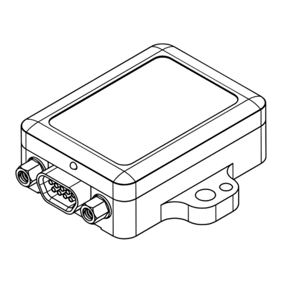
Inertial Mesurement Unit Sensor Overview User Manual 2.2 Interface and Indicators ™ The 3DM-GX4-15 sensor interface is a dual use communications and power input connector. The sensor is mounted using the mounting and alignment holes as needed (see Sensor Mounting on page 38). -
Page 10: Basic Setup And Operations
To acquire sensor measurements and computed outputs, the 3DM-GX4-15 is used with a host ® computer capable of serial communication, and a software interface. The LORD MicroStrain MIP Monitor software is provided with the system and includes all functions needed for sensor ®... -
Page 11: Software Installation
™ 3DM-GX4-15 Inertial Mesurement Unit Basic Setup and Operations User Manual 3.1 Software Installation NOTE The MIP Monitor Software Suite includes hardware drivers required for all ™ 3DM-GX4 sensors. Sensors will not be recognized without these drivers. To install MIP Monitor Software Suite on the host computer, complete the following steps: 1. -
Page 12: System Connections
To acquire sensor data the following components are needed: 3DM - GX4 - 15 sensor, communication cable, power cable, as applicable for RS232 communications, and a host ® computer with access to the data acquisition software, such as LORD MicroStrain MIP Monitor. Figure 5 - System Connections... -
Page 13: Software Interface
™ 3DM-GX4-15 Inertial Mesurement Unit Basic Setup and Operations User Manual 3.3 Software Interface The MIP Monitor software includes a main window with system information and menus, a device settings window ( see Sensor Settings on page 15 ), and several data monitoring... -
Page 14: Sensor Communication
™ 3DM-GX4-15 Inertial Mesurement Unit Basic Setup and Operations User Manual 3.4 Sensor Communication Once power has been applied to the sensor, it is on. The sensor selects the appropriate serial communication (USB or RS232) on power- up based on which cable is connected. If the hardware drivers have been installed, communication can be established using the MIP Monitor software interface. -
Page 15: Sensor Settings
™ 3DM-GX4-15 Inertial Mesurement Unit Basic Setup and Operations User Manual 3.5 Sensor Settings Device settings are stored in the sensor memory. Only the configuration options that are available for the type of sensor being used will be available in the configuration menus. - Page 16 ™ 3DM-GX4-15 Inertial Mesurement Unit Basic Setup and Operations User Manual e. Help menu: Enable the context sensitive help menu for explanations of specific settings (see Interactive Help Menu on page 13). Figure 9 - Device Settings Menu...
-
Page 17: Saving Configurations
™ 3DM-GX4-15 Inertial Mesurement Unit Basic Setup and Operations User Manual 3.5.1 Saving Configurations Sensor settings are saved temporarily in the device memory by selecting the OK button in the Device Setup window. To save the settings for future use, select Settings > Save... -
Page 18: Data Monitoring And Recording
™ 3DM-GX4-15 Inertial Mesurement Unit Basic Setup and Operations User Manual 3.6 Data Monitoring and Recording NOTE During viewing and recording, only the outputs that are selected in the Message Format tabs in the Device Setup menu are displayed and recorded (see Sensor Settings on page 15). - Page 19 ™ 3DM-GX4-15 Inertial Mesurement Unit Basic Setup and Operations User Manual There are several data monitoring views available depending on what measurements are desired for monitoring and recording. Each view corresponds to one of the main categories in ™ the Device Settings window. For example, the 3DM - GX4 - 15...
- Page 20 Microsoft Excel NOTE If the data is recorded in Binary format it will require a translation program that ® utilizes the LORD MicroStrain MIP Data Communications Protocol to make it user-readable. Figure 13 - Record Data 5.
-
Page 21: Viewing Data
™ 3DM-GX4-15 Inertial Mesurement Unit Basic Setup and Operations User Manual 3.7 Viewing Data Acquired data is stored in either Binary (.bin) or Comma Separated Values (.CSV) format, depending on what was selected at the initiation of data recording. The files can be found in the directory specified at that time or in the default directory on the host computer desktop. -
Page 22: Sensor Measurements
User Manual Sensor Measurements ™ The 3DM-GX4-15 block diagram (Figure 15 - 3DM-GX4-15™ Block Diagram ) describes its primary hardware components and internal configuration. Integrated Micro-Electro-Mechanical ™ System (MEMS) sensors within the 3DM - GX4 - 15 are collectively known as the Inertial Measurement Unit (IMU) and include tri-axial gyroscopes (gyros) and tri-axial accelerometers, and a pressure altimeter. -
Page 23: Direct Sensor Measurements (Imu Outputs)
™ 3DM-GX4-15 Inertial Mesurement Unit Sensor Measurements User Manual 4.1 Direct Sensor Measurements (IMU Outputs) The sensors in an Inertial Navigation System (INS), from which measurements for navigation and orientation are obtained, are collectively know as the Inertial Measurement Unit (IMU). - Page 24 ™ Table 4 - IMU Measurements lists the IMU measurements available for the 3DM-GX4-15 Additional measurement units may be available in MIP Monitor for some outputs however they are converted values and do not represent the actual sensor outputs. Only actual output units are listed.
-
Page 25: Computed Outputs (Estimation Filter)
™ 3DM-GX4-15 Inertial Mesurement Unit Sensor Measurements User Manual 4.2 Computed Outputs (Estimation Filter) ™ The computed outputs are measurements from the 3DM- GX4- 15 IMU sensors that are blended through an Adaptive Kalman Filter (AKF) algorithm. The Kalman Filter produces a better estimation of attitudethan can be achieved by the inertial sensors individually. - Page 26 ™ 3DM-GX4-15 Inertial Mesurement Unit Sensor Measurements User Manual Measurement Units Description indicates the current state of the EF, Filter Status such as running or initializing GPS time corresponding to the cal- GPS Time weeks & seconds culated filter solution...
-
Page 27: Sensor Reference Frames
™ 3DM-GX4-15 Inertial Mesurement Unit Sensor Measurements User Manual 4.3 Sensor Reference Frames 4.3.1 Geodetic Frame The World Geodetic System is the standard for cartography and navigation. The latest ™ revision, WGS84, is the reference coordinate system for GPS, and the 3DM- GX4-15 reports position using this coordinate frame. -
Page 28: North East Down (Ned) Frame
For most applications, this assumption is valid and provides a more intuitive reference frame for expressing velocity and attitude information than a global frame. ™ The 3DM-GX4-15 reports velocity in this frame and attitude with respect to this frame. Figure 19 -... -
Page 29: Sensor Frame
NED frame exactly, giving zero rotation. ™ The 3DM-GX4-15 reports acceleration, angular rate, delta-Theta, delta-velocity, inertial sensor biases and corrections in this frame when no sensor- to- platform frame... -
Page 30: Platform Frame
User Manual 4.3.4 Platform Frame ™ The 3DM-GX4-15 includes the option to define an orientation transformation and offset distance from the sensor frame to a user-definable platform frame. This is useful when the sensor cannot be mounted in the same location or orientation as the desired reference point on the platform frame. - Page 31 ™ 3DM-GX4-15 Inertial Mesurement Unit Sensor Measurements User Manual In the MIP Monitor software the transformation and offset settings are entered in the Settings > Device > Estimation Filter > Mounting > Mounting Orientation and Mounting Offset fields (Figure 22 - Platform Frame Settings).
-
Page 32: Performance Optimization
™ 3DM-GX4-15 Inertial Mesurement Unit Performance Optimization User Manual Performance Optimization 5.1 Gyroscope Bias Gyroscope biases (offsets) can be zeroed out to set a baseline value for the static home position and conditions in the application. This should be done after sensor installation. -
Page 33: Heading Drift And Compensation
™ 3DM-GX4-15 Inertial Mesurement Unit Performance Optimization User Manual Heading Drift and Compensation There are two options for the heading reference source: an external reference, or none. If the setting is an external reference, the user has to provide a heading reference. If the setting is none, the estimated heading will drift when little-to-no changes in velocity are sensed (e.g. -
Page 34: Angular Rate And Acceleration Limits
Most computer RS232 ports are limited to ™ 115,200 baud even though the 3DM-GX4-15 is capable of running at 921,600 baud. 5.5 Platform Frame Transformation... -
Page 35: Estimation Filter Convergence
™ The 3DM-GX4-15 runs a Adaptive Kalman Filter with a full-state dynamics model. The state propagation utilizes Newton’s and Euler’s equations of motion with the acceleration and angular rate treated as control inputs. -
Page 36: Bias Convergence
5.9 IMU Sensor Calibration ™ All of the sensor internal to the 3DM-GX4-15 are calibrated when it is manufactured and the calibration values are saved in the device memory. Recalibration should not be required unless the device has been under conditions that have exceeded the operating specifications. For example, if the sensor has been exposed to excessive shock beyond the rated g- force, performance may be compromised. -
Page 37: Temperature Compensation
™ 3DM-GX4-15 Inertial Mesurement Unit Performance Optimization User Manual 5.10 Temperature Compensation All sensor conversion and calibration formulas include temperature compensation. All computed outputs and IMU sensor outputs are automatically adjusted for local temperature (see Direct Sensor Measurements (IMU Outputs) on page 23... -
Page 38: Sensor Installation
™ 3DM-GX4-15 Inertial Mesurement Unit Sensor Installation User Manual Sensor Installation 6.1 Sensor Mounting ™ The 3DM- GX4- 15 sensor housing is rated for indoor use only, unless used inside of a protective enclosure. The sensor has two mounting tabs with holes for fastening. There are two additional holes used for precise alignment with 2mm dowel pins. -
Page 39: Oem System Integration
™ control systems that react to the sensor outputs. For these applications the 3DM-GX4-15 available as a stand-alone component with optional interface connectors. The communication protocol used for configuring and acquiring sensor data and estimations outputs is available for these applications as well. -
Page 40: Packet Builder
7.1.1 Packet Builder To expedite program development, a packet builder tool is included in the MIP Monitor ™ software. The packet builder allows users to send multiple packets to the 3DM-GX4-15 and view the resulting reply data. ™ Applicable protocol structure and design is described 3DM-GX4-15 MIP DCP Manual. -
Page 41: Sensor Direct Mode
The sensor direct mode allows programmatic access of the internal IMU which has its own processor and protocol commands. For more ® information about using this mode, contact LORD MicroStrain Technical Support (see Technical Support on page 49). -
Page 42: Sensor Wiring
® Sensor power and serial communications cables are available from LORD MicroStrain come with the sensor starter kits. These cables will have the micro-DB9 connector on one end (to connect to the sensor) and either a standard DB9 on the other end (for RS232 communication) or a USB connector (for USB communications). -
Page 43: Sampling On Start-Up
This technique will not work in MIP Monitor because it automatically puts the sensor in idle mode in order to allow device configuration. ® For more information refer to the "Startup Settings" Technical Note on the LORD MicroStrain ® website, or contact LORD MicroStrain... -
Page 44: Troubleshooting
™ 3DM-GX4-15 Inertial Mesurement Unit Troubleshooting User Manual Troubleshooting 8.1 Troubleshooting Guide... - Page 45 (See Technical Support on page 49). 1.5 sensor is damaged If all power settings and connections have been verified, and ® the sensor is still unresponsive, contact LORD MicroStrain Technical Support (See Technical Support on page 49). 2.1 sensor not found in MIP Monitor 2.
- Page 46 ™ 3DM-GX4-15 Inertial Mesurement Unit Troubleshooting User Manual Problem Possible cause and recommended solution sufficient time to detect it. See Software Installation on page 11 2.4 serial baud rate setting (not applicable to USB devices) The host computer serial port baud rate and the sensor baud settings must match in order for communication be established.
- Page 47 When data recording is started the user can choose between CSV and Binary output formats. If the data is recorded in Binary format it will require a translation program that utilizes ® the LORD MicroStrain MIP Data Communications Protocol to make it human readable. 3.5 sensor is damaged With the sensor in a static neutral position data look for baseline offset or drift on the IMU sensor outputs.
-
Page 48: Repair And Calibration
LORD MicroStrain within the warranty period. ® This warranty does not extend to any LORD MicroStrain products which have been subject to misuse, alteration, neglect, accident, incorrect wiring, mis- programming, or use in violation of operating instructions furnished by LORD ®... -
Page 49: Technical Support
Troubleshooting User Manual 8.3 Technical Support ® There are many resources for product support found on the LORD MicroStrain website including technical notes, FAQs, and product manuals. http://www.microstrain.com/support_overview.aspx For further assistance our technical support engineers are available to help with technical and applications questions. -
Page 50: Maintenance
™ 3DM-GX4-15 Inertial Mesurement Unit Maintenance User Manual Maintenance ™ There are no user-serviceable parts on the 3DM-GX4-15 . Removing the device cover or disassembling in any way will void the product warranty. -
Page 51: Parts And Configurations
For the most current product information, custom, and OEM options not listed below, refer to ® ® the LORD MicroStrain website or contact the LORD MicroStrain Sales Department. Table 6 - Model Numbers describes the standard models available at the time this manual was published. - Page 52 Components on page Figure 29 - Standard Part Numbers ® LORD MicroStrain Description Part Number 3DM-GX4-15 Starter Kit (RS232, +/-5g, 300°/sec) 6233-4221 3DM-GX4-15 Starter Kit (USB, +/-5g, 300°/sec) 6233-4241 3DM-GX4-25 Starter Kit (RS232, +/-5g, 300°/sec) 6234-4221 3DM-GX4-25 Starter Kit (USB, +/-5g, 300°/sec) 6234-4241 3DM-GX4-45 Starter Kit (RS232, +/-5g, 300°/sec)
-
Page 53: Accessories
The following parts are available for use with the 3DM-GX4 and some are included in sensor ® starter kits. For the most current product information refer to the LORD MicroStrain website or contact the Sales Department. See Sales Support on page ®... -
Page 54: Warranty Information
® use in violation of operating instructions furnished by LORD MicroStrain . It also does not extend to any units altered or repaired for warranty defect by ®... -
Page 55: Sales Support
30 days from the date of receipt for a full refund (excluding shipping and handling), as long as the product is unaltered and ® undamaged. Items can only be returned after LORD MicroStrain has issued an Return Material Authorization (RMA). Items must be packed to withstand ®... -
Page 56: Safety Information
This section provides a summary of general safety precautions that must be understood and ® applied during operation and maintenance of components in the LORD MicroStrain Inertial Sensor Products. Throughout the manual, ANSI Z535 standard safety symbols are used to indicate a process or component that requires cautionary measures. -
Page 57: References
References 12.1 Reference Documents ® Many references are available on the LORD MicroStrain website including product user manuals, technical notes, and quick start guides. These documents are continuously updated and may provide more accurate information than printed or file copies. ... -
Page 58: Glossary
™ 3DM-GX4-15 Inertial Mesurement Unit References User Manual 12.2 Glossary A/D Value The digital representation of analog voltages in an analog-to-digital (A/D) conversion. The accuracy of the conversion is dependent on the resolution of the system electronics. Higher res- olution produces a more accurate conversion. - Page 59 ™ 3DM-GX4-15 Inertial Mesurement Unit References User Manual ASTM (Association of Standards and Testing) A nationally accepted organization for testing and calibration of technological devices Attitude The orientaion of an object in space with reference to a defined frame, such as the North, East,...
- Page 60 ™ 3DM-GX4-15 Inertial Mesurement Unit References User Manual Delta-Theta The time integral of angular rate expressed with refernce to the device local coordinate system, in units of radians. Delta-velocity The time integral of velocity expressed with refernce to the device local coordinate system, in units of g*second where g is the standard gravitational constant.
- Page 61 ™ 3DM-GX4-15 Inertial Mesurement Unit References User Manual Inertial Measurement System Inclinometer Device used to measure tilt, or tilt and roll. Inertial Pertaining to systems that have inertia or are used to measure changes in inertia as in angular or linear accelerations.
- Page 62 ™ 3DM-GX4-15 Inertial Mesurement Unit References User Manual North, East, Down. A geographic reference system Original Equipment Manufacturer Offset A non-zero output signal of a sensor when no load is applied to it typically due to sensor imper- fections. Also called bias.
- Page 63 ™ 3DM-GX4-15 Inertial Mesurement Unit References User Manual system has 65536 bits. Root Mean Squared Roll In navigation roll is what occurs when a horizontal force is applied at a distance right or left from the center of gravity of the platform, causing it to move side to side with respect to the sensor or platform frame origin.
- Page 64 ™ 3DM-GX4-15 Inertial Mesurement Unit References User Manual UTC (Coordinated Universal Time) The primary time standard for world clocks and time. It is similar to Greenwich Mean Time (GMT). Vector A measurement with direction and magnitude with refernce from one point in space to another Velocity The rate of change of position with respect to time.
Need help?
Do you have a question about the 3DM-GX4-15 and is the answer not in the manual?
Questions and answers