Table of Contents
Advertisement
Quick Links
Advertisement
Table of Contents

Related Manuals for Lord MicroStrain 3DM-CX5-10


Summary of Contents for Lord MicroStrain 3DM-CX5-10
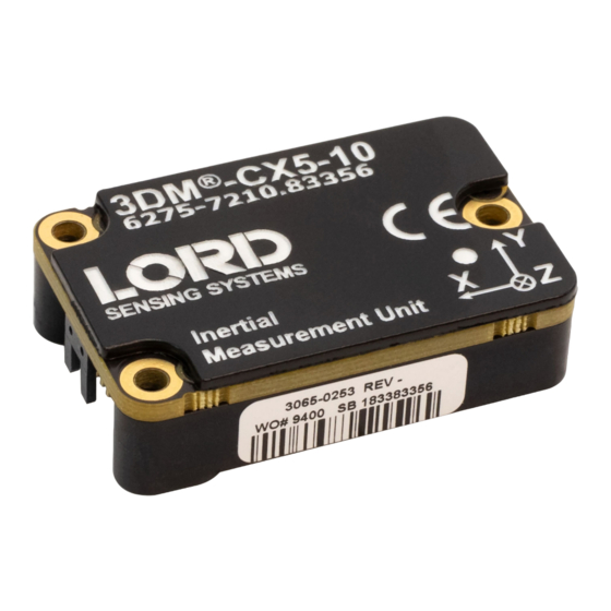
- Page 1 LORD USER MANUAL -CX5-10 ® Inertial Measurement Unit (IMU)
- Page 2 , Little ® ® ® ® ® ® ® ® ® Sensors, Big Ideas. ® , LORD Microstrain ® , Live Connect™, LXRS ® , MathEngine ® , MicroStrain ® , MIP™, MXRS ® , Node Commander , SensorCloud™, SensorConnect™, SG-Link...
-
Page 3: Table Of Contents
-CX5-10 USER MANUAL ® Contents 1. System Family Overview ................1 2. Sensor Overview ....................2 Components ....................3 Interface and Indicators ................4 Basic Setup and Operations ..............5 Software Installation ................6 System Connections ................7 Software Interface ...................8 3.3.1 Interactive Help Menu ..............8 Sensor Communication ................9 Sensor Settings ..................10 3.5.1 Saving Configurations ..............11 Data Monitoring and Recording ............12... - Page 4 -CX5-10 USER MANUAL ® 6. Sensor Installation ..................22 Sensor Mounting ...................22 7. System Integration ..................23 Data Communications Protocol (DCP) ..........23 Packet Builder ..................23 Sensor Wiring ..................24 Sampling on Start-up ................25 Connecting to a Datalogger ..............26 Using Wireless Adapters ...............26 8. Troubleshooting ..................27 Troubleshooting Guide ................27 Repair and Calibration ................30 Technical Support .................30...
-
Page 5: System Family Overview
-CX5-10 USER MANUAL ® System Family Overview The LORD Sensing 3DM-CX5 family of high-performance, industrial-grade, board-level inertial sensors provides a wide range of triaxial inertial measurements and computed attitude and navigation solutions. In all models, the Inertial Measurement Unit (IMU) includes direct measurement of acceleration and angular rate, while some offer atmospheric pressure readings. -
Page 6: Sensor Overview
All sensor measurements are temperature-compensated and are mathematically aligned to an orthogonal coordinate system. The combination of sensors and environmental compensation allows the 3DM-CX5-10 to perform well in a wide variety of applications that require low noise, drift, gain, and offset errors. and bias estimation outputs are available. -
Page 7: Components
® Components The 3DM-CX5-10 Inertial Sensor can be purchased by itself or as part of a Development Kit. All software, drivers, and links to detailed documentation are included with the sensor purchase. For a complete list of available configurations, accessories, additional system... -
Page 8: Interface And Indicators
The 3DM-CX5-10 sensor interface includes a communications and power input connector. The sensor is installed using the mounting and alignment holes as needed. The indicators on the 3DM-CX5-10 include a device status indicator and the device information label. The table below describes the basic status indicator behavior. includes the sensor frame diagram (axis orientation), which will be critical during device installation. -
Page 9: Basic Setup And Operations
® Basic Setup and Operations To acquire sensor measurements and computed outputs, the 3DM-CX5-10 uses a host computer, an RS232 serial communications port, and applicable software. The LORD Sensing MIP Monitor software is provided with the system and includes all functions needed for sensor configuration and data acquisition. -
Page 10: Software Installation
-CX5-10 USER MANUAL ® Software Installation NOTE: The MIP Monitor Software Suite includes hardware drivers required for 3DM- CX5-10 sensor operation. Sensors will not be recognized without these drivers installed. To Install the MIP Monitor software on the host computer, complete the following steps: 1. -
Page 11: System Connections
Use only power supplies within the operating range of the sensor, or damage or injury could result. Once power is applied the sensor is on and active. To acquire sensor data the following components are needed: 3DM-CX5-10 sensor, communication cable, power cable (as applicable for RS232 communications), connectivity board, and a host computer with LORD Sensing MIP Monitor installed. -
Page 12: Software Interface
-CX5-10 USER MANUAL ® Software Interface The MIP Monitor software includes a main window with system information and menus, a device settings window, and several data monitoring windows. The main window provides an overview of connected devices. Devices are selected by clicking on them. -
Page 13: Sensor Communication
-CX5-10 USER MANUAL ® Sensor Communication Once power has been applied to the sensor, it is functional. If the hardware drivers have been installed, communication can be established using the MIP Monitor software interface. 1. Verify the sensor device status indicator is on. 2. -
Page 14: Sensor Settings
To enter the settings menu, either right-click on the sensor name highlighted in the main window, and then select Device Settings, or select Settings > Device from the main menu. For the 3DM-CX5-10 these include: Main menu tabs: The main tabs divide the settings into functional groups for the available measurements. -
Page 15: Saving Configurations
-CX5-10 USER MANUAL ® 3.5.1 Saving Configurations Sensor settings are saved temporarily by selecting the OK button in the Device Setup window after configuration, but they are lost when the device is powered off. To save current settings, so they are automatically restored the next time the device is powered on, select Settings > Save Current Settings. -
Page 16: Data Monitoring And Recording
Each view corresponds to one of the main categories in the Device Settings window. For example, the 3DM-CX5-10 includes Sensor Data Monitoring for the IMU/AHRS measurements. During viewing and recording, only the outputs that are selected in the Message Format tab are displayed and recorded. - Page 17 -CX5-10 USER MANUAL ® Figure 12 - Data Streaming is an example of Sensor Data Monitoring, which displays the selected IMU/AHRS measurements. In data monitoring windows, no data will be displayed until data streaming is started, and no data will be recorded (even if it is being viewed) until data recording is initiated (armed).
-
Page 18: View Recorded Data
-CX5-10 USER MANUAL ® View Recorded Data Recorded data is stored in either Binary (.bin) or Comma Separated Values (.csv) format, depending on what was selected at the initiation of data recording. The files can be found in the directory specified at that time or in the default directory on the host computer desktop. CSV files can be viewed with Microsoft Excel, Quattro Pro, Open Office, or other CSV editors and spreadsheet programs. -
Page 19: Sensor Measurements
The 3DM-CX5-10 block diagram describes its primary hardware components and internal configuration. Integrated Micro-Electro-Mechanical System (MEMS) sensors within the 3DM-CX5-10 are collectively known as the Inertial Measurement Unit (IMU) and include tri-axial gyroscopes (gyros) and tri-axial accelerometers. This technology provides direct measurements of acceleration, angular rate, Delta-theta (change in angular rate), and Delta- velocity (change in velocity). -
Page 20: Direct Sensor Measurements (Imu Outputs)
Figure 15 - IMU Settings Table 2 - IMU Measurements lists the IMU measurements available for the 3DM-CX5-10. Additional measurement units may be available in MIP Monitor for some outputs, however they are converted values and do not represent the actual sensor outputs. Only actual output... -
Page 21: Sensor Reference Frames
-CX5-10 USER MANUAL ® Measurement Units Description three axis acceleration readings in Acceleration gravitational force (g) engineering units three axis rotational velocity reading from Angular Rate radian/second gyroscope in engineering units time integral of angular rate with configurable Delta Angle (Theta) radians time period time integral of acceleration with configurable... -
Page 22: North East Down (Ned) Frame
-CX5-10 USER MANUAL ® 4.2.2 North East Down (NED) Frame The North-East-Down (NED) frame is a local coordinate frame, which is formed by a tangent plane located at a particular point (current coordinates) on the WGS84 reference ellipse. The NED frame is constructed with the (true) North vector along the line of longitude, the East vector along the line of latitude, and the Down vector normal to and towards the tangent plane. -
Page 23: Sensor Frame
NED frame exactly, giving zero rotation. The 3DM-CX5-10 reports acceleration, angular rate, delta-theta, and delta-velocity n this frame. Refer to the 3DM-CX5-10 dimensional diagram for the location of the measurement origin. Figure 18 - Sensor Frame... -
Page 24: Performance Optimization
Overrunning the communication bandwidth will result in dropped data packets. Most computer RS232 ports are limited to 115,200 baud even though the 3DM-CX5-10 is capable of running at 921,600 baud. -
Page 25: Imu Sensor Calibration
® IMU Sensor Calibration All of the internal sensors in the 3DM-CX5-10 are calibrated when the device is manufactured, and the calibration values are saved in the device memory. Recalibration is not required unless the device has been under conditions that exceed the operating specifications. For example, if the sensor has been exposed to excessive shock beyond the rated g-force, performance may be compromised. -
Page 26: Sensor Installation
-CX5-10 USER MANUAL ® Sensor Installation Sensor Mounting See the CX5 Interface Control Document for detailed drawings and mounting instructions. The sensor has three holes for fastening to ensure maximum stability. Mounting fasteners should be 2- 56 x ½” button head screws, either brass or 300 series stainless steel. The sensor can be mounted in any orientation, as required for the application. -
Page 27: System Integration
Data Communications Protocol (DCP) The LORD Sensing MIP Data Communications Protocol (DCP) includes all commands available for controlling and acquiring data from the 3DM-CX5-10, including many that are not available in the MIP Monitor software. Programming is performed through a standard serial interface program. -
Page 28: Sensor Wiring
-CX5-10 USER MANUAL ® Figure 22 - Packet Builder Sensor Wiring See the CX5 Interface Control Document for detailed drawings and instructions on wiring the 3DM- CX5 family of inertial sensors. Only use power supplies within the operating range of the sensor, or permanent sensor damage could result. -
Page 29: Sampling On Start-Up
Logic Level Disable (Open or Low = Enable) Mounting Holes Chassis Chassis Ground * USB is not available on the 3DM-CX5-10 and may be left connected to USB or unconnected. Figure 23 - Pin Locations and Functions Sampling on Start-up The Save Current Settings command can be used to instruct the sensor to start streaming data as soon as it powered on. -
Page 30: Connecting To A Datalogger
-CX5-10 USER MANUAL ® To save the current sensor configuration, first adjust the sensor settings to the desired values, and then start streaming. Next select Settings > Save Current Settings from the main window. The setting will remain intact when the sensor is powered off and then on again. To recall the last saved settings select Settings >... -
Page 31: Troubleshooting
-CX5-10 USER MANUAL ® Troubleshooting Troubleshooting Guide... - Page 32 -CX5-10 USER MANUAL ® Possible cause and recommended solution Problem 1.1 no power is applied The status indicator on the device will be off. Make sure the 1. POWER sensor is connected to a power source and the status indicator illuminates.
- Page 33 -CX5-10 USER MANUAL ® Possible cause and recommended solution Problem 2.5 sensor or cables are damaged Verify all connections, power, and settings. If available, try installing an alternate cable or sensor one at a time to see if the faulty device can be identified. If no conclusion can be determined, or to send a device in for repair, contact LORD Sensing Technical Support.
-
Page 34: Repair And Calibration
-CX5-10 USER MANUAL ® Repair and Calibration General Instructions In order to return any LORD Sensing product, you must contact LORD Sensing Sales or Technical Support to obtain a Return Merchandise Authorization (RMA) number. All returned merchandise must be in the original packaging, including manuals, accessories, cables, etc. with the RMA number clearly printed on the outside of the package. -
Page 35: Parts And Configurations
-CX5-10 USER MANUAL ® Parts and Configurations Standard Configurations For the most current product information, custom, and OEM options not listed below, refer to the LORD Sensing website or contact the LORD Sensing Sales Department. Table 3 - Model Numbers describes the standard models available at the time this manual was published. - Page 36 -CX5-10 USER MANUAL ® The same options are available in each model, and are indicated in the last four digits of the product part number. For a list of the starter kit contents, (see Components on page Figure 25 -Standard Part Numbers...
-
Page 37: Accessories
-CX5-10 USER MANUAL ® Accessories The following parts are available for use with the 3DM-CX5-10. For the most current product information refer to the LORD Sensing website or contact the Sales Department. LORD Sensing Part Description Number RS232 development kit... -
Page 38: Specifications
-CX5-10 USER MANUAL ® 10. Specifications General Integrated sensors Triaxial accelerometer, triaxial gyroscope, and temperature sensors Inertial Measurement Unit (IMU) outputs: acceleration, angular Data outputs rate, delta theta, delta velocity Inertial Measurement Unit (IMU) Sensor Outputs Accelerometer Gyroscope ±8 g (standard) 300°/sec (standard) Measurement range ±75, ±150, ±900°/sec (optional) - Page 39 -CX5-10 USER MANUAL ® Operating Parameters Communication TTL serial (3.0 V dc, 9,600 bps to 921,600 bps, default 115,200) Power source +4 to + 36 V dc Power 300 mW (typ) consumption 500 mW (typ) Operating -40 °C to +85 °C temperature 500 g (calibration unaffected) Mechanical shock...
-
Page 40: 3Dm-Cx5 Sensors
-CX5-10 USER MANUAL ® 10.1 3DM-CX5 Sensors See the CV5 Interface Control Document for detailed diagrams, notes and references on the 3DM-CX5 family of inertial sensors. Figure 26 - 3DM-CX5 Sensor 10.2 3DM-CX5 Development Kit See the 3DM-CX5 Reference Design Documentation for detailed drawings and notes on the components included in the development kit. -
Page 41: Reference Documents
Many references are available on the LORD Sensing website including product user manuals, technical notes, and quick start guides. These documents are continuously updated and may provide more accurate information than printed or file copies. Document Where to find it 3DM-CX5-10 support documentation http://www.microstrain.com/documents/inertial NIST Calibration Procedures http://www.nist.gov/calibrations/ ASTM Testing Procedures http://www.astm.org/Standard/standards-and-publications.html... -
Page 42: Safety Information
Situations where a non-immediate or potential hazard presents a risk to damage of property and equipment. May be used to indicate important operational conditions. 12.1 Maintenance There are no user-serviceable parts on the 3DM-CX5-10. Removing the device cover or disassembling in any way voids the product warranty. 12.2 Disposal and Recycling The 3DM-CX5-10 contains internal printed circuit boards and electronic components.