Table of Contents
Advertisement
Quick Links
Advertisement
Table of Contents

Related Manuals for Lord MicroStrain G-Link-200-OEM


Summary of Contents for Lord MicroStrain G-Link-200-OEM
- Page 1 LORD USER MANUAL G-Link -200-OEM ® Wireless Accelerometer Node...
- Page 2 , Little ® ® ® ® ® ® ® ® ® Sensors, Big Ideas. ® , LORD Microstrain ® , Live Connect™, LXRS ® , MathEngine ® , MicroStrain ® , MIP™, MXRS ® , Node Commander , SensorCloud™, SensorConnect™, SG-Link...
-
Page 3: Table Of Contents
1. Wireless Sensor Network Overview .............1 2. Node Overview ....................2 Figure 1. G-Link-200-OEM ..............2 2.1 Configuration Options ................3 Table 1. G-Link-200-OEM Configuration Options ........3 2.2 Parts ......................4 Table 2. G-Link-200-OEM Parts ............4 2.3 Interface and Indicators ................5 Figure 2. Interface and Indicators ............5 Table 3. - Page 4 G-Link-200 OEM USER MANUAL 4. Wireless Sensor Configuration ..............11 4.1 Hardware Configuration ................11 Figure 11. Node Configuration Menu ...........11 Table 4. Group Delay ................11 Table 5. High Pass Filter Values ............12 4.2 Calibration Configuration .................12 Figure 12. Wireless Sensor Calibration Menu ........12 4.3 Sampling Configuration ................13 Figure 13.
- Page 5 G-Link-200 OEM USER MANUAL Figure 20. Sampling Operations Menu ..........21 Figure 21. Event Triggered Sampling ..........22 5.6 Output Operation ..................23 Figure 22. Data Outputs ...............23 6. Viewing Data ....................24 6.1 Sensor Cloud ...................24 6.1.1 Connect to SensorCloud ..............24 Figure 23. SensorCloud Log-in or Register .........24 6.1.2 Navigating Menus ................25 Figure 24.
- Page 6 G-Link-200 OEM USER MANUAL 7.2 Optimizing the Radio Link ................32 7.2.1 Range Test ..................33 Figure 34. Range Test Menu ...............33 Figure 35. Range Test Statistics ............33 7.3 Data Type ....................34 Figure 36. Data Type Menu ..............34 8. Troubleshooting ..................35 8.1 Troubleshooting Guide ................35 8.2 Updating Node Firmware .................38 8.3 Repair and Calibration ................38 General Instructions .................38...
-
Page 7: Wireless Sensor Network Overview
G-Link-200-OEM USER MANUAL Wireless Sensor Network Overview The LORD Sensing Wireless Sensor Network is a high-speed, scalable, sensor data acquisition and sensor networking system. Each system consists of wireless sensor interface nodes, a data collection gateway, and full-featured user software platforms based on the LORD Sensing Lossless Extended Range Synchronized (LXRS) and data communications protocol. -
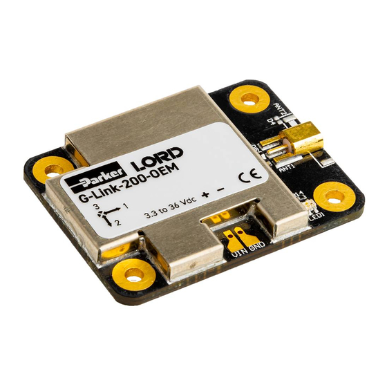
Page 8: Node Overview
Velocity (IPSrms), Amplitude (Grms and Gpk-pk) and Crest Factor, allowing long-term monitoring of key performance indicators while maximizing battery life. To acquire sensor data, the G-Link-200-OEM is used with a LORD Sensing WSDA gateway, and comes with the following configuration options. -
Page 9: Configuration Options
G-Link-200-OEM USER MANUAL 2.1 Configuration Options G-Link-200-OEM sensor node comes with the following configuration options. Product Model Part Number G-Link-200-OEM integrated chip antenna 6305-6002 6305-6003 G-Link-200-OEM, MMCX IP67 whip antenna 6305-6181 6305-6141 G-Link-200-OEM, U.FL stub antenna 6305-6182 6305-6142 Table 1. G-Link-200-OEM Configuration Options... -
Page 10: Parts
G-Link-200-OEM USER MANUAL 2.2 Parts The following parts are available for the G-Link-200-OEM Part Description Part Number Power connector and mating cable (factory Power Interface Kit 6306-1030 installation available at time of purchase) Mounting Kit Mounting base and 4 screws... -
Page 11: Interface And Indicators
G-Link-200-OEM USER MANUAL 2.3 Interface and Indicators Figure 2. Interface and Indicators Indicator Behavior Node Status Node is OFF Rapid green flashing on start-up Node is booting up Node is idle and waiting for a 1 (slow) green pulse per second... - Page 12 G-Link-200-OEM USER MANUAL Figure 3. Node Operational Modes...
-
Page 13: System Operation
G-Link-200-OEM USER MANUAL System Operation The gateway is the interface between LORD Sensing sensor nodes and the data acquisition computer. The gateway coordinates the configuration and sampling of the nodes and can handle many nodes simultaneously. Communication between the nodes and gateway is wireless and uses the LORD Sensing LXRS and LXRS+ data communications protocols. -
Page 14: Gateway Communication
3.3.1 Automatic Node Discovery on Same Frequency If the base and node are on the same operating frequency, the node will populate below the Base Station listing when powering on the G-Link-200-OEM. Figure 5. Node Discovered On Same Frequency... -
Page 15: Automatic Node Discovery On Different Frequency
G-Link-200-OEM USER MANUAL 3.3.2 Automatic Node Discovery on Different Frequency If a red circle with a number appears next to the Base Station, the node is operating on a separate radio channel. Select the Base Station and then select the Nodes on Other Frequencies tile. - Page 16 G-Link-200-OEM USER MANUAL If the node was successfully added, two confirmation messages will appear and it will be listed under the Base Station. Figure 9. Add Node Confirmation If the node failed to be added, a failure message will appear. This means the node did not respond to the base station which could indicate the node is not in idle mode or it may be on another frequency.
-
Page 17: Wireless Sensor Configuration
G-Link-200-OEM USER MANUAL Wireless Sensor Configuration 4.1 Hardware Configuration Node settings are stored to non-volatile memory and may be configured using SensorConnect. This chapter describes the user-configurable settings. Figure 11. Node Configuration Menu Input Range - Set the accelerometer range to fit the application. Available ranges are ±2.048 g, ±4.096 g, and ±8.192 g for the 8g node or ±10.24 g, ±20.48 g, and ±40.96 g for the... -
Page 18: Calibration Configuration
G-Link-200-OEM USER MANUAL High Pass Filter - The accelerometer contains an optional high-pass filter which is disabled by default. The high-pass filter corner frequency is effected by the low pass filter setting. When enabled, the high pass filter -3 dB point will be equal to the corresponding low pass filter value as shown in Table 5 below. -
Page 19: Sampling Configuration
G-Link-200-OEM USER MANUAL 4.3 Sampling Configuration There are three user-set sampling options for the G-Link-200-OEM, including Lost Beacon Timeout, Diagnostic Info Interval, and Storage Limit Mode, in the Wireless Node Configuration > Sampling menu. Figure 13. Sampling Configuration Menu Lost Beacon Timeout - When the node is running in a synchronized network, it periodically synchronizes its time clock to a beacon broadcasted from the WSDA gateway. - Page 20 G-Link-200-OEM USER MANUAL The contents of the diagnostic packet may be viewed in the Data tab within SensorConnect. Description Data Values Data Type Unit 0 = Idle 1 = Deep sleep Current State unit 8 2 = Active run 3 = Inactive run...
-
Page 21: Power
G-Link-200-OEM USER MANUAL 4.4 Power There are multiple user-set power options for the G-Link-200-OEM, including Default Operation Mode, User Inactivity Timeout, Check Radio Interval, and Transmit Power, in the Wireless Node Configuration > Power menu. Figure 14. Node Configuration Power Menu Default Operation Mode - When power is applied, the node will enter the Default Operation Mode. -
Page 22: Wireless Sensor Sampling Configuration
G-Link-200-OEM USER MANUAL Wireless Sensor Sampling Configuration 5.1 Start Collecting Data There are several ways to collect data from the G- Link- 200- OEM, including from a single node, a network of nodes, or restarting the last used sampling mode, by pressing and holding the start button until the LED light turns blue. -
Page 23: Network Options
G-Link-200-OEM USER MANUAL 5.2 Network Options There are two network settings available for the G-Link-200-OEM: LXRS and LXRS+. These feature node-to-node synchronization of 50us, and unmatched lossless wireless sensor network data throughput. MicroStrain Sensing created these specifically for applications such as flight test and heavy machinery monitoring, where large amounts of raw data are generated, and node synchronization is important. -
Page 24: Raw Waveform Channels
• Useful when your application requires consistent latency or can tolerate lost data. 5.3 Raw Waveform Channels There are two options for data output from the G-Link-200-OEM, including raw waveform channels and derived data channels. The raw channels provide waveform data directly from the sensor. -
Page 25: Derived Output Channels
G-Link-200-OEM USER MANUAL 5.4 Derived Output Channels There are four derived data channels available for the G-Link-200. Using these data channels for vibration analysis allows the ability to extend battery life while reducing data. Each operation is performed on a window of data from the specified accelerometer axis. -
Page 26: Chunks
Chunk size is defined below where p is the derived period, d is the burst duration, and is the maximum chunk size. Maximum chunk size can change between nodes depending on how many resources are available for derived calculations. The G-Link-200-OEM has a max chunk size of 256 samples. -
Page 27: Under-Sampling
The more input signal periods sampled within a window the more accurate the calculation. 5.5 Sampling Operations Options There are four sampling operations options for the G-Link-200-OEM, including Continuous, Limited, Periodic Burst, and Event Triggered. Figure 20. Sampling Operations Menu... - Page 28 G-Link-200-OEM USER MANUAL • Continuous - Collect data continuously at the configured sample rate. All data is transmitted and/or logged to flash memory until a Set to Idle command is received. • Limited - Automatically stop sampling and return to Idle mode after the configured time duration is met.
-
Page 29: Output Operation
G-Link-200-OEM USER MANUAL 5.6 Output Operation There are three options for managing data acquired from the G-Link-200-OEM. The user can transmit collected data, log the data to flash memory, or do both. Figure 22. Data Outputs... -
Page 30: Viewing Data
G-Link-200-OEM USER MANUAL Viewing Data 6.1 Sensor Cloud SensorCloud is based on cloud computing technology and is designed for long term collecting and preservation of data. Features include time series and visualization graphing, automated alerts, and data interpretation tools such as data filtering, statistical analysis, and advanced algorithm development with the integrated MathEngine interface. -
Page 31: Navigating Menus
G-Link-200-OEM USER MANUAL 6.1.2 Navigating Menus The SensorCloud interface has six main views. When logging in as a registered user, the Device view is the default. Navigate to other views by clicking the view name at the top of the page. The Data and Settings views are only available once a device is selected from the device list. - Page 32 G-Link-200-OEM USER MANUAL Figure 25. SensorCloud Data View Settings - The settings view provides options for adding meta-data, configuring the data displays for each channel, creating alerts based on data thresholds, setting the data time zone, and more. MathEngine - is used to analyze sensor data. Functions include the ability to filter out ®...
- Page 33 G-Link-200-OEM USER MANUAL Figure 26. MathEngine® View Figure 27. FFT Graph in SensorCloud For more information about SensorCloud features and navigation, refer to the SensorCloud website or contact LORD Sensing Support.
-
Page 34: Sensorconnect
G-Link-200-OEM USER MANUAL 6.2 SensorConnect 6.2.1 Using Dashboards and Widgets Collected data is viewed on the Data page through the creation of dashboards and widgets. Think of dashboards as individual pages and widgets as an illustration on the page. Create multiple data widgets on each dashboard to display sampled data as a time-series graph, text chart, or a simple gauge that only displays the most current reading. -
Page 35: Widgets Options
G-Link-200-OEM USER MANUAL 6.2.3 Widgets Options The widget configuration menu is different for each type of widget but typically includes sensor or channel selections and widget settings such as titles and legends. After adding a widget, left click to select and configure it in the Channels and Settings left sidebar menu. -
Page 36: Exporting Data Files
G-Link-200-OEM USER MANUAL 6.2.5 Exporting Data Files To export data to a .csv file, select the Export Data button on the Time Series widget > Export > name the document > save to the preferred location on the host computer. -
Page 37: Installation
Installation 7.1 Mounting Recommendations The G-Link-200-OEM is rated for indoor use only, unless housed in a ruggedized outdoor enclosure. There are 4 mounting holes on the G-Link-200-OEM for 2-56 UNC screws.The node can be mounted in any orientation, but it is recommended that it is mounted in a way that optimizes wireless communications. -
Page 38: Optimizing The Radio Link
G-Link-200-OEM USER MANUAL 7.2 Optimizing the Radio Link NOTE In the event of communication difficulties, it may be necessary to disable WIFI on the host computer, or use a USB extender when collecting data. The best method for ensuring optimal radio communication is to conduct an RF survey of the installation site. -
Page 39: Range Test
G-Link-200-OEM USER MANUAL 7.2.1 Range Test After establishing communication between node and gateway, use the range test feature in SensorConnect to monitor the signal strength and to optimally position the nodes, gateway, and antennae for installation. Maximum achievable range is determined by the gateway and node power settings (found in the device Configure menu) and is highly dependent on the physical environment surrounding the devices. -
Page 40: Data Type
G-Link-200-OEM USER MANUAL 7.3 Data Type There is a 20-bit ADC on the G-Link-200-OEM. However, users may select the data type that is reported. Floating point should be selected in most applications and where nodes must send measurements in units of g-force. Int16 or Int24 may be selected for applications requiring maximum network bandwidth or longer battery life. -
Page 41: Troubleshooting
G-Link-200-OEM USER MANUAL Troubleshooting 8.1 Troubleshooting Guide... - Page 42 G-Link-200-OEM USER MANUAL Possible cause and recommended solution 1.1 node or gateway power is off The status indicator LED on the device may be off. Turn the device on, and the status indicator LED should illuminate. 1. POWER 1.2 node battery is dead Gateway or node does If the node will not power on, the node battery may need to be replaced.
- Page 43 G-Link-200-OEM USER MANUAL Possible cause and recommended solution 3.1 no communication to node or gateway Verify connections and power to the node and gateway. Verify they are powered on and communicating with the software. Enter a configuration menu to verify that the node can be accessed.
-
Page 44: Updating Node Firmware
G-Link-200-OEM USER MANUAL 8.2 Updating Node Firmware Under the recommendation of LORD Sensing Technical Support Engineers, nodes can be upgraded to the latest available firmware to take advantage of new features or correct operating settings. SensorConnect version 5.0.0 or greater can be used to update any LXRS node or gateway firmware to the most current version. -
Page 45: Specifications
G-Link-200-OEM USER MANUAL Specifications 9.1 Physical Specifications Dimensions 38.1 mm x 6.5 mm x 29 mm Mounting 4 x 2-56 UNC Weight 8.17 grams Conformal Coating Humiseal 1B31... -
Page 46: Operating Specifications
G-Link-200-OEM USER MANUAL 9.2 Operating Specifications Specifications Analog Input Channels 40 g Measurement range ±2 g, ±4 g, or ±8 g configurable ±10 g, ±20 g, or ±40 g configurable Noise density 25 µg/√ Hz 80 µg/√ Hz 0 g offset ±25 mg (±2 g) -
Page 47: Mechanical Shock Limits
G-Link-200-OEM USER MANUAL RF transmit power User-adjustable 0 dBm to 20 dBm. Restricted regionally Power source 3.3 V dc to 36 V dc to solder pads Tx Power VIN = 3.6 V VIN = 5.0 V VIN = 12 V... -
Page 48: Safety Information
10.2 Replacing Batteries 1. Remove the cap from the G-Link-200-OEM. 2. Remove the three ½ AA batteries from the G-Link-200-OEM. 3. Insert three new ½ AA batteries (Saft LS 14250 recommended), observing the correct polarity orientation. The positive polarities are indicated on the batteries and the node by a “+”... -
Page 49: Battery Hazards
10.5 Radio Specifications The G-Link-200-OEM employs a 2.4GHz IEEE 802.15.4- compliant radio transceiver for wireless communication. The radio is a direct- sequence spread spectrum radio and can be configured to operate on 16 separate frequencies ranging from 2.405 GHz to 2.480 GHz. -
Page 50: References
G-Link-200-OEM USER MANUAL 11. References 11.1 Technical Support There are many resources for product support found on the LORD Sensing website including technical notes, FAQs, and product manuals. http://www.microstrain.com/support_overview.aspx For further assistance our technical support engineers are available to help with technical and applications questions. -
Page 51: Related Documents
G-Link-200-OEM USER MANUAL 11.3 Related Documents References are available on the LORD Sensing website including product user manuals, technical notes, and quick start guides. They may provide more accurate information than printed or file copies. Document Where to find it Online Wireless Network Calculator http://sensorcloud.com/?onlyCalc=true...
Need help?
Do you have a question about the G-Link-200-OEM and is the answer not in the manual?
Questions and answers