
Related Manuals for Westerbeke 3.5 MCGA 60 Hz


Summary of Contents for Westerbeke 3.5 MCGA 60 Hz
- Page 1 M U LT I - P O RT S I N G L E – P H A S E MARINE GASOLINE GENERATORS OPERATORS MANUAL 3.5 MCGA 60 Hz 3.5 MCGA 50 Hz PART NUMBER 057563 REVISION C May 2023...
- Page 2 In no event shall Westerbeke, publishers, authors, or editors of this guide be liable for any loss of profit or any other commercial damage caused or alleged to have been caused directly or indirectly by this document.
- Page 3 MTBE is no longer a primary concern since it is no longer available.) sludge, or gums entering or forming in the engine or fuel system is not covered by the Westerbeke Corporation limited warranty. Ethanol is a solvent and tends to clean any dirt or contaminants on contact.
-
Page 4: Table Of Contents
Operators Manual for Gasoline Generators 1 Important Safety Information C O N T E N T S 1 Important Safety Information 2 Introduction Quick Start Operators Guide ........................4 Documentation ............................4 Parts Diagram ............................5 Warranty Procedures ..........................6 Conventions Used in this Manual ...................... - Page 5 Operators Manual for Gasoline Generators 1 Important Safety Information Lay-Up Prep: Intake Manifold ......................... 45 Lay-Up Prep: Spare Parts......................... 45 How to Recommission After a Lay-Up ..................... 45 9 Generator Specifications Specifications: Engine ..........................47 Specifications: Fuel System ........................47 Specifications: Electrical System ......................
- Page 6 Operators Manual for Gasoline Generators L I S T O F F I G U R E S Figure 1: Parts Diagram ............................5 Figure 2: Customer Identification Card ......................... 6 Figure 3: Product Serial Number, Model Number, and Other Specifications ............6 Figure 4: Spare Parts Kit ............................
-
Page 7: Important Safety Information
Operator Manual for Gasoline Generators 1 Important Safety Information ▪ All fuel vapors are highly explosive. Use extreme care when handling and storing fuels. Store fuel in a well-ventilated area away from spark- Important Safety Information producing equipment and out of the reach of children. ▪... - Page 8 CO poisoning is one of the major safety risks associated with exhaust gas with an appropriate CO analyzer. boating. It is a threat that must not be underestimated. Westerbeke There are two locations where exhaust gas can be sampled: multiport EFI generators are designed to dramatically reduce normal levels of CO in the engine exhaust.
- Page 9 Control System consists of engine design and precision Scientific, GFG, TPI, Teledyne, and others. manufacturing. ▪ Westerbeke recommends analyzers with a probe connected to the Engine Valve analyzer by a length of transparent tubing. They are slightly more Adjustment expensive than those with the sensor built-in to one end of the analyzer,...
-
Page 10: Introduction
Operator Manual for Gasoline Generators 2 Introduction This Westerbeke generator is a product of our many years of experience and advanced technology. We take great pride in the superior durability and dependable performance of our engines and generators. Thank you for selecting Westerbeke. -
Page 11: Parts Diagram
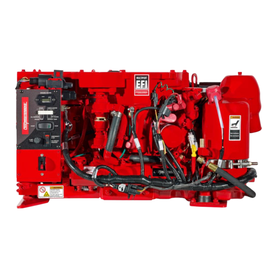
Operator Manual for Gasoline Generators 2 Introduction Parts Diagram PARTS IDENTIFICATION 3.5 MCGA GENERATOR Figure 1: Parts Diagram page... -
Page 12: Warranty Procedures
2 Introduction Operator Manual for Gasoline Generators Warranty Procedures Your Westerbeke Warranty Statement is included in the product documentation package. Complete and return the included warranty registration card or register your product online at www.westerbeke.com. You should receive your customer warranty identification card in the mail within 30 days of registering. -
Page 13: Conventions Used In This Manual
Westerbeke distributor or dealer. Checklist: Protecting Your Investment Care at the factory during assembly and thorough testing have resulted in a Westerbeke generator capable of many hours of dependable service. However, the manufacturer cannot control where the generator is installed in the vessel or how well the unit is installed, operated, and serviced in the field. -
Page 14: Amperage Drain
Spare Parts, Kits, and Accessories Certain spare parts will be needed to support and maintain your Westerbeke generator. Your local Westerbeke dealer will assist you in preparing an inventory of suggested spare parts and accessories. TIP: We also recommend carrying enough spare engine oil for an oil change and one gallon of premixed coolant for the cooling system. -
Page 15: Figure 4: Spare Parts Kit
Operator Manual for Gasoline Generators 2 Introduction Figure 4: Spare Parts Kit The Parts Kit image is generic and does not correspond to this particular model. For your convenience, we offer two spare part kits, each packaged in a water-tight storage case: Kit A includes the basic set of the most essential recommended spare parts. -
Page 16: Figure 5: Suggested Spare Parts
2 Introduction Operator Manual for Gasoline Generators Figure 5: Suggested Spare Parts page... -
Page 17: Installation
Operator Manual for Gasoline Generators 3 Installation 3 Installation NOTE: When installing Westerbeke engines and generators, pay strict attention to all installation requirements. In addition to the installation information in this chapter of this guide, also refer to the Marine Installation Manual supplied with your product. -
Page 18: Exhaust System Requirements
When installing this kit, apply a thin coat of clean oil to the O-ring and the filter gasket where the filter contacts the base. Tighten firmly by hand. Thread on the optional Westerbeke remote oil filter kit. Always install this kit with the oil filter facing down. -
Page 19: Figure 7: Remote Oil Fill (Detailed View)
If there is no oil pressure reading, shut down immediately and check the hose connections. NOTE: Westerbeke is not responsible for engine failure due to the improper installation of the remote oil filter. -
Page 20: Startup And Basic Operation
Then follow the oil and filter change intervals as specified in 5.1: Maintenance Schedule. See 5.4.3. for proper procedures for filling oil. Westerbeke does not approve or disapprove the use of synthetic oils. If synthetic oils are used, engine break-in must be performed using conventional oil. The required oil change intervals are listed in this manual and cannot be extended, even if synthetic oils are used. -
Page 21: Coolant Recovery Tank
Operator Manual for Gasoline Generators 4 Startup and Basic Operation The distilled water and antifreeze should be pre-mixed before being poured into the cooling circuit. Refer to section 5.3 for filling the cooling system. TIP: Use the environmentally-friendly, long-lasting antifreeze that is now available. A proper 50/50 mixture as recommended will protect the engine coolant at temperatures as low as -40°... -
Page 22: How To Start And Stop The Generator
4 Startup and Basic Operation Operator Manual for Gasoline Generators fuel flow through the bleed hose and when no air bubbles are seen, close the bleed valve and observe the fuel pressure. The pressure should be in the 40-psi range. Remove the pressure gauge set and replace the caps on the two Schrader valves. -
Page 23: Figure 10: Control Panel Dc Circuit Breaker And Start/Stop Switch
Operator Manual for Gasoline Generators 4 Startup and Basic Operation NOTE: This position is also used to prime the fuel system when necessary. See 4.6 How to Bleed the Fuel System. green LED dims indicating the engine has shut down. Figure 10: Control Panel DC Circuit Breaker and Start/Stop Switch 4.7.2 How to Start and Stop the Generator (Remote Control Panel) -
Page 24: Safety Shutdown Switches And Leds
4 Startup and Basic Operation Operator Manual for Gasoline Generators The start/stop rocker switch functions the same as the start/stop rocker switch on the generator control panel as previously explained. green LED run indicator light on the rocker switch is illuminated when the generator is running. -
Page 25: Figure 12: Exhaust Temperature Switch
Operator Manual for Gasoline Generators 4 Startup and Basic Operation NOTE: The CHECK ENGINE light indicates a possible emissions control problem. Immediate action should be taken to troubleshoot and correct this problem. The EXT ALARM light indicates a fault with the fire suppression circuit. Troubleshoot the circuit to determine the fault (the fire suppression circuit must be closed when the circuit is active). -
Page 26: Figure 13: Coolant Temperature Sensor
4 Startup and Basic Operation Operator Manual for Gasoline Generators coolant temperature. Should the temperature reach an overheat threshold, the ECU will shut the engine down and will illuminate the engine temperature fault LED light on the control panel. Figure 13: Coolant Temperature Sensor 4.8.5 DC Circuit Breaker The engines electrical system is protected by a 20-amp manual reset circuit breaker. -
Page 27: Break-In Procedure For Daily Operation
Operator Manual for Gasoline Generators 4 Startup and Basic Operation Break-In Procedure for Daily Operation After starting the generator, check for proper operation and then allow the generator to warm up a few minutes before applying a load. Run the generator between 20% and 60% of full- load for the first 10 hours. -
Page 28: Checklist: Daily Startup
4 Startup and Basic Operation Operator Manual for Gasoline Generators Figure 15: Engine Oil and Coolant System Components 4.11 Checklist: Daily Startup Follow this check list each day before starting your generator. ❑ Visually inspect the generator for fuel, oil, water leaks or loose parts. ❑... -
Page 29: Maintenance
Operator Manual for Gasoline Generators 5 Maintenance 5 Maintenance Maintenance Schedule The maintenance intervals specify operating hours or a time interval, whichever comes first. For example, if maintenance is due every 250 hours or six months, and you have logged 300 hours in only two months, do not delay maintenance another four months. - Page 30 5 Maintenance Operator Manual for Gasoline Generators 5.1.3 Every 50 Operating Hours or Monthly Drive Belts: Inspect drive belts in fresh water or raw water pump applications for ❑ proper tension (3/8” to 1/2” deflection) and adjust if needed. Check belt for slipping, cracking and wear.
-
Page 31: Maintenance: Fuel System
Operator Manual for Gasoline Generators 5 Maintenance 5.1.8 Every 1,000 Hours or Every Five Years Engine Timing Belt: Remove and replace the timing belt. ❑ CAUTION: Failure to replace the timing belt at the recommended interval could result in timing belt failure resulting in major damage to the engine. -
Page 32: Figure 17: Harness Lift Pump Dc Auxiliary Power Adapter
5 Maintenance Operator Manual for Gasoline Generators These filters must meet U.S. Coast Guard specifications, which typically means these gasoline filters must have metal bowls (not see-through). The metal bowls have drain valves to use when checking for water and contaminants. 5.2.2 Fuel Pump Periodically check the fuel connections to and from the pump. -
Page 33: Maintenance: Cooling System
5.3.1 Fresh Water Cooling Circuit Westerbeke marine engines are designed and equipped for fresh water cooling. Heat produced in the engine by combustion and friction is transferred to fresh water, which circulates throughout the engine. This circulating fresh water cools the engine block and its internal moving parts The heat is transferred externally from the fresh water to sea water by means of a heat exchanger, similar in function to an automotive radiator. -
Page 34: Figure 19: Cooling System Heat Exchanger (Left) And Thermostat (Right)
5 Maintenance Operator Manual for Gasoline Generators Premix fresh coolant and distilled water or use Pre-mixed 50/50 coolant. Open the air bleed petcock on the water jacketed exhaust manifold and slowly pour new pre-mixed coolant into the open filler neck until coolant is visible in the filler neck. Start the engine. - Page 35 Operator Manual for Gasoline Generators 5 Maintenance 5.3.4 Cooling System Zinc Anode A zinc anode (or pencil) in the raw water cooling circuit in the heat exchanger sacrifices itself to electrolysis action taking place in the raw-water cooling circuit, reducing the effects of electrolysis on other components of the system.
-
Page 36: Maintenance: Engine
5 Maintenance Operator Manual for Gasoline Generators producing the pumping action. There should always be a spare impeller and impeller cover gasket aboard (an impeller kit). Raw water pump impeller failures occur when raw water is not present during engine operation. -
Page 37: Figure 20: Engine Oil Filter, Dip Stick, Drain Hose And Oil Fill Cap
Screw the filter onto the threaded oil filter stub. Where the filter contacts the base, tighten firmly by hand. TIP: Use genuine Westerbeke oil filters. Generic filters are not recommended. 5.4.3 How to Refill the Engine Oil Add fresh oil through the valve cover. -
Page 38: Figure 21: Engine Oil Dipstick, Low, Correct Level And Overfull Mark
5 Maintenance Operator Manual for Gasoline Generators Figure 21: Engine Oil Dipstick, Low, Correct Level and Overfull Mark 5.4.4 How to Inspect the Spark Plugs It is important to maintain spark plugs in a proper operating condition. They are an important component in the ignition system in lowering carbon monoxide levels. -
Page 39: Figure 23: Air Screen/Flame Arrestor
Operator Manual for Gasoline Generators 5 Maintenance 5.4.5 How to Clean the Air Screen/Flame Arrestor The air screen/flame arrestor should be cleaned after the first 50 hours of operation. Then refer to the maintenance schedule in this manual. Clean using a good dish washing solution, rinse, and air dry. Inspect the seal edges. -
Page 40: Figure 25: Battery Charger
5 Maintenance Operator Manual for Gasoline Generators 5.4.7 Battery Charging Circuit The battery charger is an encapsulated, solid-state unit that supplies DC charging voltage to the generator starting battery while the generator is operating. The battery charging circuit is powered by a separate stator coil under the flywheel. The unit senses the needs of the starting battery and supplies a DC charge when one is needed. -
Page 41: Figure 26: Catalyst Installation
CO while the engine is running. This must be performed with a CO analyzer. WARNING : Never reuse an exhaust sealing gasket. Always replace with a new gasket. NOTE: For information on installing exhaust systems, see the Installation Manual available at www.westerbeke.com. Figure 26: Catalyst Installation page... -
Page 42: Maintenance: Connections, Motors, And Circuit Breakers
5 Maintenance Operator Manual for Gasoline Generators Maintenance: Connections, Motors, and Circuit Breakers Maintaining reasonable cleanliness is important to avoid corrosion on terminal board connections and rectifiers. Take steps to prevent the accumulation and build-up of salt, dust, engine exhaust particulates, and carbon, especially on insulation surfaces. Clogged ventilation openings may cause excessive heating and reduce the life of windings. -
Page 43: Figure 27: Ac Circuit Breaker (50 & 60Hz)
5.5.4 AC Circuit Breaker A circuit breaker is installed on all single-phase Westerbeke generators. This circuit breaker will automatically disconnect generator power in case of an electrical overload. The circuit breaker can be manually shut off when servicing the generator to ensure that no power is being supplied into the boat. -
Page 44: Figure 28: Bc Generator Ac Terminal Connection Schematic
5 Maintenance Operator Manual for Gasoline Generators Figure 28: BC Generator AC Terminal Connection Schematic page... -
Page 45: Figure 29: Shore Power Transfer Switch
Shore Power Transfer Switch If the installer connects shore power to the AC circuit on your vessel, this must be done by means of a shore power transfer switch. Ship-to-shore switches are available from Westerbeke or an authorized dealer. Figure 29: Shore Power Transfer Switch Set the transfer switch shown in the diagram to the OFF position. -
Page 46: Diagnostics And Troubleshooting
The diagnostic software runs on most Microsoft Operating Systems. It requires a minimum of 128 MB of RAM. The communications cable plugs into a USB port. NOTE: The Westerbeke communications cable is unique to this diagnostic software and must be used. An incompatible cable may damage the ECU. -
Page 47: Engine Troubleshooting
Operator Manual for Gasoline Generators 6 Diagnostics and Troubleshooting Engine Troubleshooting The following troubleshooting chart describes common engine problems and possible causes. CAUTION: When servicing the engine/generator, turn off the main AC circuit breaker to disconnect all AC power. Problem: Possible Cause: Engine does not crank: 1. - Page 48 6 Diagnostics and Troubleshooting Operator Manual for Gasoline Generators 4. Fuel starvation. 5. Throttle body malfunction. External alarm LED is illuminated: 1. Loose connection. 2. Faulty fire suppression shutdown device. page...
-
Page 49: Wiring Diagrams
Operator Manual for Gasoline Generators 7 Wiring Diagrams 7 Wiring Diagrams The Wiring Diagram is available online and a printed copy is included in the standard equipment kit with your generator. Remote Start/Stop Panels Figure 32: Wiring Diagram for Start/Stop Panel with Fault Display NOTE: A 15-foot or 30-foot extension harness is also available. -
Page 50: Lay-Up And Recommissioning
8 Lay-Up and Recommissioning Operator Manual for Gasoline Generators 8 Lay-Up and Recommissioning Many owners rely on their boatyards to prepare their craft, including engines and generators, for lay-up during the off-season or for long periods of inactivity. Others prefer to accomplish lay-up preparation themselves. -
Page 51: Lay-Up Prep: Starter Motor
Lay-Up Prep: Spare Parts Lay-up time provides an opportunity to inspect your Westerbeke engine to see if external items such as drive belts or coolant hoses need replacement. Check your basic spares kit and order items not on hand, or replace those items used during the lay-up, such as filters and zinc anodes. - Page 52 8 Lay-Up and Recommissioning Operator Manual for Gasoline Generators Remove the raw water pump cover and gasket and discard the old gasket. Install the raw water pump impeller removed during lay-up (or a replacement, if required). Install the raw water pump cover with a new cover gasket. Reinstall the batteries that were removed before the lay-up period, and reconnect the battery cables.
-
Page 53: Generator Specifications
Operator Manual for Gasoline Generators 9 Generator Specifications 9 Generator Specifications Specifications: Engine Item Description Engine Type 2-cylinder, 4-cycle, overhead camshaft water cooled gasoline engine Bore & Stroke 2.40 x 2.24 inches (61.0 x 57.0 mm.) Total Displacement 20.32 cubic inches (0.333 liters) Combustion Chamber Semi-spherical Compression Ratio... -
Page 54: Specifications: Cooling System
9 Generator Specifications Operator Manual for Gasoline Generators Specifications: Cooling System Item Description General Fresh water-cooled block through raw water-cooled heat exchanger circuit Fresh Water Pump Positive displacement, rubber impeller, belt-driven Raw Water Pump Positive displacement, rubber impeller, belt-driven Raw Water Flow Rate 3.4 US gpm (12.9 liters per minute) @ 2500 rpm (approx. -
Page 55: 9.9 Specifications: Engine Component Tightening Torque
Operator Manual for Gasoline Generators 9 Generator Specifications 9.9 Specifications: Engine Component Tightening Torque Engine Component Ft. Lbs. Timing Belt Flywheel Bolt 86-88 63-65 Timing Belt Cover Bolts 10-12 Camshaft sprocket bolts 80-100 58-72 Oil pump sprocket nuts 50-57 36-41 Timing tensioner nuts 22-30 16-22... - Page 56 9 Generator Specifications Operator Manual for Gasoline Generators Oil pressure switch 12-18 9-13 Oil pressure sender 12-18 9-13 Water drain plug 35-45 25-33 Water Pump Water pump 8-10 page...
- Page 57 Operator Manual for Gasoline Generators 9 Generator Specifications This page intentionally left blank. page...
- Page 58 9 Generator Specifications Operator Manual for Gasoline Generators ©2022 Westerbeke, Inc. All Rights Reserved. Westerbeke Corporation Myles Standish Industrial Park 150 John Hancock Rd. Taunton, MA 02780-7319 USA Phone: (508) 823-7677 FAX: (508) 884-9688 www.westerbeke.com page...
Need help?
Do you have a question about the 3.5 MCGA 60 Hz and is the answer not in the manual?
Questions and answers
Type of coolant used in 3.5MCCA
The Westerbeke 3.5 MCGA 60 Hz uses a 50/50 mixture of good quality antifreeze and distilled water. The antifreeze should contain supplemental cooling additives (SCAs) and be pre-mixed before being added to the cooling system.
This answer is automatically generated