Table of Contents
Advertisement
Quick Links
SERVICE MANUAL
4-CYLINDER
MARINE DIESEL ENGINES
& GENERATORS
MARINE DIESEL ENGINES
38B FOUR
W-33
42B FOUR
W-27
W-33A
R08D
W-27A
MARINE DIESEL GENERATORS
WMD 11.0-60Hz
WMD 8.3-50Hz
11.0 BTO
WMD 12.5-60Hz
12.5 BTDA
WMD 9.4-50Hz
9.4 BTDA
12.5 BTD
8.3 BTD
9.4 BTD
PUBLICATION NO. 43440
2nd Edition / April 1998
WESTERBEKE CORPORATION· MYLES STANDISH INDUSTRIAL PARK
150 JOHN HANCOCK ROAD, TAUNTON, MA 02780-7319 U.S.A.
Advertisement
Table of Contents
Troubleshooting

Related Manuals for Westerbeke 38B FOUR


Summary of Contents for Westerbeke 38B FOUR
- Page 1 12.5 BTDA WMD 11.0-60Hz WMD 9.4-50Hz 9.4 BTDA WMD 8.3-50Hz 11.0 BTO 12.5 BTD 8.3 BTD 9.4 BTD PUBLICATION NO. 43440 2nd Edition / April 1998 WESTERBEKE CORPORATION· MYLES STANDISH INDUSTRIAL PARK 150 JOHN HANCOCK ROAD, TAUNTON, MA 02780-7319 U.S.A.
- Page 2 CALIFORNIA PROPOSITION 65 WARNING Diesel engine exhaust and some of its constituents are known to the State of California to cause cancer, birth defects, and other reproductive harm. WARNING Exhaust gasses contain Carbon Monoxide, an odorless and colorless gas. Carbon Monoxide is poisonous and can cause unconsciousness and death.
- Page 3 SAFETY INSTRUCTIONS INTRODUCTION PREVENT BURNS - FIRE Read these safety instructions carefully. Most accidents are caused by failure to follow fundamental rules and precau- WARNING: Fire can cause injury or death! tions. Know when dangerous conditions exist and take the necessary precautions to protect yourself, your personnel, •...
- Page 4 SAFETY INSTRUCTIONS ACCIDENTAL STARTING TOXIC EXHAUST GASES WARNING: Carbon monoxide (CO) is a deadly gas! WARNING: Accidental starting can cause injury or death! • Ensure that the exhaust system is adequate to expel gases discharged from the engine. Check the exhaust system •...
- Page 5 SAFETY INSTRUCTIONS ing adjustments, use extreme care to avoid touching ABYC, NFPA AND USCG PUBLICATIONS FOR moving parts and hot exhaust system components. INSTALLING DIESEL ENGINES • Do not wear loose clothing or jewelry when servicing Read the following ABYC, NFPA and USCG publications equipment;...
- Page 6 Engines & Generators...
-
Page 7: Table Of Contents
TABLE OF CONTENTS Introduction ................. Engine Shutoff ..............Product Software ..............3 Engine with Manual Stop (Standard) ........32 Engine/Generator Model Designations ......... Optional Key Switch Shutoff (38B and 42B only) .... .32 Notes, Cautions and Warnings ..........Installing and Adjusting the Key Switch Ordering Parts/Serial Number Location ........ - Page 8 TABLE OF CONTENTS Reassembly ................48 Engine Wiring Diagram.#36467 .......... 70 Drive Belt Adjustment ..........48 Engine Wiring Schematic #36467 ........71 Engine Wiring Diagram #36844 .......... 72 Admiral Control Panel ............Engine Wiring Schematic #36844 ........73 Description ................49 Engine Wiring Diagram #39144 ..........
-
Page 9: Introduction
The necessary procedures should be undertaken lows: only by such facilities and their personnel. Refer also to your NOTE: An operating procedure essential to note. Westerbeke parts catalog when performing an engine over- haul. PRODUCT SOFTWARE CAUTION: Procedures, which if not strictly... - Page 10 INTRODUCTION Owners may find it convenient to fill in the data on the decal or identification nameplate shown below to provide a quick reference when using this service manual. SPECIFICATION 50 HZ. MODEL _______ _ RPM ... _________ _ KW _____ ... _____ _ KVA __________ _ VOLTS _ ...
-
Page 11: Engine/Generator Specifications
C MODELS GENERATORS GENERATORS GENERATORS ENGINES ENGINES ENGINES 60Hz 50Hz 60Hz 50Hz 60Hz 50Hz 38B Four 11.0 BTD 8.3 BTD W-33 WMD 12.5 WMD 9.4 428 Four 12.5 BTDA 9.4 BTDA WMD 11.0 WMD 8.3 W-33A 12.5 BTD 9.4 8TD... -
Page 12: Testing For Overhaul
TESTING FOR OVERHAUL HOW TO JUDGE ENGINE OVERHAUL PERIOD 5. Install a pressure gauge adapter in the first injector hole or glow plug hole to be tested. Cause of Low Compression 6. Connect the pressure gauge to the adapter. Generally, the time at which an engine should be overhauled 7. -
Page 13: Reassembly
TESTING FOR OVERHAUL 5. Perfonn disassembly in a proper order using proper tools. Keep disassembled parts in order. Apply oil when neces- sary. Take special care to keep the fuel system parts free from the intrusion of dust and dirt. Reassembly 1. -
Page 14: Service Standards
SERVICE STANDARDS These SERVICE STANDARDS specify the values at which A MODElS B MODELS C MODELS the engine components will require REPAIR (replacement is GENERATORS GENERATORS GENERATORS ENGINES ENGINES ENGINES optional), or REPLACEMENT (due to maximum component 60Hz 50Hz 60Hz 50Hz 60Hz 50Hz... - Page 15 SERVICE STANDARDS All measurements are in mm unless otherwise noted. To convert mm to inches, multiply by .03937 REPAIR (or DESCRIPTION MODELS STANDARD VALUE replacement) REPLACEMENT Required at: Required at: PISTON 0.0. (skirt end) 0.07-0.08 Piston to cylinder clearance .178 0.3 BIO Oversize 0.25, 0.50, 0.75...
- Page 16 SERVICE STANDARDS All measurements are mm unless otherwise noted. h i ' 0393 o convert mm to mc es, mu tlply bv . REPAIR (or DESCRIPTION MODELS STANDARD VALUE replacement) REPLACEMENT Required at: Required at: CAMSHAFT Front bearing Lead bronze alloy with back metal Oil clearance 0.04 - 0.08 0.10...
-
Page 17: Technical Data
TECHNICAL DATA TIGHTENING TORQUE DESCRIPTION MODELS TYPE/QUANTITY TIGHTENING TORQUE (kg-m) (10) CYLINDER HEAD BOLT M12 bolt 11.5 - 12.5 (wet) 6.5 - 8.0 (wet) M10 bolt M14 bolt (10) 15 -16 M14 bolt (4) tappet side 10 -11 CRANKSHAFT PULLEY NUT M18t 15 -20 20-25... -
Page 18: Engine Troubleshooting
ENGINE TROUBLESHOOTING The following troubleshooting table describes certain Note: The engine electric..al system is protected by a 20- problems relating to engine service, the probable causes of ampere manual reset circuit breaker located on a bracket on these problems, and the recommendations to overcome the left front side of the engine. - Page 19 ENGINE TROUBLESHOOTING PROBLEM PROBABLE CAUSE VEmFICATION/REMEDY LOW OUTPUT OVERHEATING (cont.) 1. Low coolant level. 1. Add coolant. 2. Adjust or replace V~belt. 2. Loose V-belt. 3. Incorrect injection timing. 3. Adjust injection timing. 4. Low engine oil level. 4. Add engine oil. EXCESSIVE OIL OIL LEAKAGE 1.
- Page 20 ENGINE TROUBLESHOOTING PROBLEM PROBABLE CAUSE VERtFICATION/REMEDY (cont., (cont., SMOKY EXHAUST WHITISH OR PURPLISH d. Worn valve stem and valve guide. d. Replace. e. Low engine oil viscosity. e. Replace. Excessive oil pressure. 1. Correct. 3. Injection timing is too late. 3.
- Page 21 ENGINE TROUBLESHOOTING VERIFICATION/REMEDY PROBLEM PROBABLE CAUSE KNOCKING ENGINE KNOCKS WITHOUT MUCH SMOKE 1. Faulty injector. 1. Foul exhaust - rebuild injector. 2. Bent rod. 2. Fuelish exhaust check compression, repair. 3. Main engine troubles. a. Overheated cylinder. a. See OVERHEATING; LOW OUTPUT. b.
-
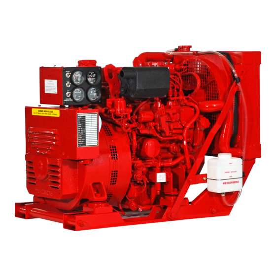
Page 22: Engine Parts Identification
ENGINE PARTS IDENTIFICATION EXHAUST VALVE CYLINDER HEAl TAPPET DRIVE BELT---" CAMSHAFT REAR OIL SEAL ,CRANKSHAFT FLYWHEEL CRANKSHAFT PULlEY GEAR CASE CBANKSHAFT GEAR OIL SCREEN SIDE VIEW INTAKE SILENCER EXHAUST MANIFOLD NOZZLE HOLDER CYLINDER HEAO \~-#++-:+----PISTON PU~P INJECTION CONNECTING ROD Il-I----PUSH ROD JIII ... -
Page 23: Cylinder Head
CYLINDER HEAD CONSTRUCTION The cylinder head gasket is made of carbon graphite. It is provided with stainless steel sheet grommets around the The cylinder head is of an overhead valve type made of bores for improved heat and pressure resistance. The gasket high-rigidity special cast iron and has an excel1ent cooling requires no sealant when assembled. -
Page 24: Cylinder Head Service
CYLINDER HEAD SERVICE DISASSEMBLY 3. Check the lower surface of the cylinder head for distor- tion using a straight edge and a feeler 1. Remove the air breather pipe. Remove the water bypass hose if provided. 2. Remove the fuel injection lines. 3. -
Page 25: Valve
CYLINDER HEAD SERVICE 3. Check the valve seat sinkage by measuring the installed length of each valve assembly. When measuring the size up to the top of the valve spring retainer, include retainer ± thickness (at the conar) of 1.7 0.3 mm. -
Page 26: Partial Reassembly
CYLINDER HEAD SERVICE Partial Reassembly 3. Be sure to use only new gaskets and packings. Apply sealant to the specified sealing points. 1. Press in the valve guides to the specified height. (For the installation procedure, see Valve Guide.) Valve Clearance Adjusbnent 2. -
Page 27: Cylinder Block
CYLINDER BLOCK CONSTRUCTION The piston pins are hollow, carbonized forgings. When con- necting a piston to its rod, a piston pin is press-fitted into the The special iron casting cylinder block is of a full jacket small end of the rod. type in which cylinder liners are integrated with the cylinder The piston rings are made of special cast iron. - Page 28 CYLINDER BLOCK chilI~ The tappet and push rod. The tubular type tappets are hardened at the bottom and gas-carburized at low tempera- ture over the entire surface to improve wear resistance. Each tappet is offset from the cam center to prevent uneven wear of the tappet bottom.
-
Page 29: Cylinder Block Service
CYLINDER BLOCK SERVICE DISASSEMBLY CAUTION: Do not hammer a piston pin tD 1. For removal of a the cylinder head and related parts, refer to DISASSEMBLY under CYLINDER HEAD SERVICE. remDve it. A stuck piston pin which requires exces- sive pulling force should be replaced. Do not apply 2. -
Page 30: Piston, Piston Pin And Piston Rings
CYLINDER BLOCK SERVICE 2. Check the water jacket for scale and corrosion. Clean the 3. Measure the side clearance between each piston ring and block thoroughly and ensure that all oil passages are its groove. If necessary, replace the ring. clean. -
Page 31: Connecting Rod
CYLINDER BLOCK SERVICE Connecting Rod (JOURNAL) 1. Using a connecting rod aligner, check each connecting R2.5~ rod for bending and distortion. If necessary, correct or replace the rod. 2. Measure the connecting rod thrust clearance with a rod assembled on the crankshaft. If the clearance is exces- (PIN) R 2.5 sive, replace the rod assembly. -
Page 32: Gearcase
CYLINDER BLOCK SERVICE Gearcase Check the gearcase body for cracks and damage, and the oil seal for damage. Also check the governor related parts. If the camshaft thrust plug press-fitted in the gearcase has been worn or damaged, install a new thrust plug. ±... - Page 33 CYLINDER BLOCK SERVICE 1. When the camshaft front bushing is pressed in, align the 4. Install the main bearings to the cylinder block. bushing oil hole with the oil hole in the cylinder block NOTE: The oil ports must be properly positioned and the using a bushing installing tool.
- Page 34 CYLINDER BLOCK SERVICE 9. Install the oil seal into the crankshaft rear oil seal case. h. Insert the assembled push rod, piston pin and guide Install the seal case to the cylinder block. Remember to into the piston pin hole from the guide side, and into install the gasket.
- Page 35 CYLINDER BLOCK SERVICE NO.1 ~BNO.; PISTON RING POSITIONS ~~NO.3 PISTON, <lOll PISTON RINGS ,.§>' RING GAP '~~. POSITIONS GEA~ MATING MARKS ENGINE FRONT ~'1" 18. Align the mating mark on the idler gear with that on the crankshaft gear; install the idler gear on the idler shaft.
- Page 36 CYLINDER BLOCK SERVICE INSTALLING GEAR CASE INSTALLING INJECTION PUMP 22. Insert the crankshaft pulley. Install the washer and nut. Then tighten to the specified torque. 28. Install the oil pump and oil filter (see REASSEMBLY under LUBRICATION SYSTEM SERVICE). When the oil 23.
-
Page 37: Governor
GOVERNOR DESCRIPTION 3. Remove the fuel injection pump (see Fuel Injection Pump under FUEL SYSTEM) The governor keeps engine speed constant by using a bal- 4. Remove the gear case mounting bolts and remove the ance between the centrifugal force acting on the governor gear case (see CA UTION under DISASSEMBLY, CYLIN- weights and the tension of the governor spring. -
Page 38: Engine Shutoff
ENGINE SHUTOFF ENGINES WITH MANUAL STOP (Standard) pull-in lead should be run to the heavy solenoid terminal on the starter. Connect the red hold lead (splice into) the A manual stop lever is located on the outboard side of the "R"... -
Page 39: Engine Adjustments
ENGINE ADJUSTMENTS TIGHTENING THE CYLINDER HEAD The engine's valves must be adjusted in this order while the valves are closed. You may find that turning the Pull off the air breather pipe from the rocker cover and engine's crankshaft is more easily accomplished when remove the rocker cover. -
Page 40: Adjusting No-Load Engine Speeds
·50 INJECTION TIMING MARKS 3750 +0 38B Four, 42B Four 2. When the specified injection timing is not correct, increase or decrease the shim material thickness under a. Seal the above-mentioned adjusting bolt with its brass the fuel injection pump. Injection timing varies 1° with cap and crimp it on the bolt. -
Page 41: Lubrication System Service
LUBRICATION SYSTEM SER\(ICE DESCRIPTION OIL PUMP ASSEN\BL Y The lubrication system uses a trochoid gear pump and a full FILTER flow oil filter. The oil pump is driven through the Oldham's coupling at the rear end of the fuel injection pump camshaft. OIL PRESSURE SWITCH Oil from the oil pump flows into the cartridge type oil filter... -
Page 42: Reassembly
LUBRICATION SYSTEM SERVICE TESTING THE OIL PRESSURE Rotor to cover clearance. With the outer rotor inserted in the pump body, insert a straightedge and check the clear- 1. Start and warm up the engine. ance between the rotor and the straightedge with a feeler 2. -
Page 43: Fuel System
FUEL SYSTEM for easy engine start. For the injection pump with the FUEL/WATER Angleich mechanism, over-injection requires releasing that . SEPARATOR mechanism. ALL WESTERBEKE ENG'lNEiGENERATOR INSTALLATIONS REQUIRE AN OWNER·INSTALLED SE~ARATOR. (7.5:-200 FUEL/WATER. MICRONS) Fuel Pump. Two types of fuel lift pumps are shown in the illustration;... - Page 44 FUEL SYSTEM Angleich Mechanism. The Angleich Mechanism restricts the The intercylinder injection control. Fuel injection control movement of the smoke set plate in the narrower range among the cylinders is performed by the adjusting plates (Angleich effect "L") to save fuel consumption and decrease which have their own cam mechanisms.
-
Page 45: Fuel System Service
FUEL SYSTEM SERVICE DISASSEMBLY a. Remove the delivery valve holder. Take out the valve spring, valve and O-ring. Fuel Filter c. Take out the gasket and valve seat. Remove the retaining nut, O-ring and filter element. d. Unbend the lock plate of the tappet guide pin. Push the Fuel Pump Lift... -
Page 46: Injector
FUEL SYSTEM SERVICE Injector 1. Disconnect the return pipe from the nozzle holder upper nipple. 2. Disconnect the fuel injection pipe from the nozzle holder. 3. Loosen the nozzle holder attaching bolts and remove the holder assembly. 4. When disassembling the nozzle holder into parts, use the following procedure: Holding the nozzle holder body in a vice, remove the retaining nut with a spanner wrench. -
Page 47: Installation And Adjustment Of Fuel Injection Pump
FUEL SYSTEM SERVICE 3. Install the spring seat gasket and the valve assembly in before inserting the tappet guide pin and bend the lock the holder. Tighten the delivery holder to the pump hous- plate after inserting the pin. ing. Make certain that the O-ring has been properly installed. -
Page 48: Injector
FUEL SYSTEM SERVICE 2. Install the tie-rod cover. In the case of a damper spring- Adjustment and Installation of Nozzle loaded cover, install the cover with the tie-rod pressed Holder Assembly toward the High Speed side by the speed control lever (see illustration). - Page 49 FUEL SYSTEM SERVICE 3. After-drip test. An injection nozzle is considered defec- tive if drips fuel accumulated on the bottom of the noz- zle after fuel injection is stopped during the chattering test. Replace such a nozzle. A very small amount of fuel may sometimes remain on the top of the nozzle.
-
Page 50: Raw Water Cooling Circuit
RAW WATER COOLING CIRCUIT DESCRIPTION The heat exchanger functions as part of the fresh water sys- tem and the raw water system. The heat exchanger is a cop- The raw water cooling circuit is driven by a positive dis- per tube which encloses a number of small copper tubes. placement impeller pump. -
Page 51: Raw Water Pump Service
RAW WATER PUMP SERVICE RAW WATER PUMP - PN 33636 PUMP OVERHAUL 2. Install the shaft into the bearings. Support the bearings at their center races. Push the shaft into the bearings, push- Disassembly ing at the impeller drive slot end using the base of the The pump, as removed from the engine, will have hose drive slot. -
Page 52: Pump Overhaul- Raw Water Pump Pn 24143
RAW WATER PUMP SERVICE RAW WATER PUMP - PN 24143 Pump #24143 has been replaced by pump #33636. Complete ment bushing, chill the bushing in a freezer for 1 hour to reduce it's size. Prepare the pump housing on a press to #24143 pumps are no longer assembled but their component parts are still available. -
Page 53: Fresh Water Cooling Circuit
FRESH WATER COOLING CIRCUIT DESCRIPTION The water temperature switch and the water temperature sender are both mounted in the thermostat housing. The The fresh water cooling circuit consists of a circulatory belt- water temperature switch, normally open in a propUlsion driven water pump, a thermostat and thermostat housing, engine, when activated, will close and sound an alarm. -
Page 54: Fresh Water Cooling Service
FRESH WATER COOLING SERVICE DISASSEMBLY Thermostat Visually check the thermostat for damage. Then put it in 1. Drain the cooling water. A drain plug for draining the engine block is located on the side of the engine block water and raise the water temperature to test its valve open- ing temperature. -
Page 55: Admiral Control Panel
ADMIRAL CONTROL PANEL DESCRIPTION oJ!, When the engine is shut down with the key switch turned the water temperature gauge will continue to register the last This manually-operated control panel is equipped with a temperature reading indicated by the gauge before electrical KEY switch and RPM gauge with an ELAPSED TIME power was turned off. -
Page 56: Captain Control Panel
CAPTAIN CONTROL PANEL DESCRIPTION' OIL PRESSURE or high WATER TEMPERATURE. The RPM gauge is illuminated when the KEY switch is turned This manual1y-operated control panel is equipped with a and remains i1Iuminated while the engine is in operation. KEY switch, an RPM gauge, PREHEAT and START but- tons, an INSTRUMENT TEST button and three indicator lamps, one for ALTERNATOR DISCHARGE, one for low OIL PRESSURE, and one for high ENGINE COOLANT... -
Page 57: Control Panel Troubleshooting
CONTROL PANEL TROUBLESHOOTING TACHOMETER/HOURMETER Tachometer Inaccurate The tachometer!hounneter used in propulsion engine instru- 1. With a hand-held tach on the front of the crankshaft pul- ment panels contains two separate electrical circuits with a ley retaining nut or with a strobe-type tach, read the front common ground. -
Page 58: Manual Starter Disconnect (Toggle Switches)
CONTROL PANEL TROUBLESHOOTING {TOGGLE MANUAL STARTER DISCONNECT SWITCHES} NOTE: The engine control system protected by a 20 amp manual reset circuIt breaker mounted on a bracket at the rear of the engine near the PREHEAT circuit. PROBLEM PROBABLE CAUSE VERIFICAnON/REMEDY PREHEAT depressed, no panel indications, 1. -
Page 59: Control Panel - Early Models
CONTROL PANEL - EARLY MODELS ACTIVATION BY KEY SWITCH overheat condition ex-ists and the operating temperature of the engine reaches 205°F, and sounds the alarm. The Turning the ignition switch ON activates the instrument tachometer will register the engine speed as it takes impulses panel. -
Page 60: Starter/Solenoid Service
STARTER/SOLENOID SERVICE DESCRIPTION 2. Lightly push the pinion back and measure the return stroke (called pinion gap). The swrtercan be roughly divided into the following sections: 3. If the pinion gap is not within the standard range (0.5 to • A motor section which generates a drive power. -
Page 61: Solenoid
STARTER/SOLENOID SERVICE 3. Holding test. With a battery connected to the solenoid SOLENOID terminal "S" and to the starter body, manually pu)) out Perform the following tests. If any test result is not satisfac- the pinion fully. The pinion must remain at that position tory, replace the solenoid assembly. -
Page 62: Starter Inspection
STARTER/SOLENOID SERVICE CLEANING THE COMMUTATOR STARTER INSPECTION Solenoid Inspect the solenoid for continuity between terminals S and M and between terminals S and body. No continuity should be found between Sand M. Continuity should be found between S and the body and M and the body. COmNUITY CHECK Brush and Brush Holder Inspection... -
Page 63: Field Coil Inspection
STARTER/SOLENOID SERVICE Field Coil Inspection 1. Check for insulation between one end (brush) of the coil and yoke. Check for continuity between both ends (brushes) of the coil. Check the poles and coil for tightness. 2. Greasing. Whenever the starter has been overhauled, apply grease to the following parts: Armature shaft gear and reduction gear. -
Page 64: Dc Electrical System
DC ELECTRICAL SYSTEM DESCRIPTION NOTE: An isolator with a diode, a solenoid, or a ballery selector switch is usually mounted in the circuit to isolate the gener~ The DC Circuit functions to start, operate and stop the balleries so the starling battery is not discharged along with ator's engine. -
Page 65: Battery Maintenance
DC ELECTRICAL SYSTEM BAmRY MAINTENANCE WARNING: These glow plugs will become very hot Review the manufacturer's recommendations and then estab- lish a systematic maintenance schedule for your engine's to the touch. Be careful not to bum your fingers when starting batteries and house batteries. testing plugs. -
Page 66: Alternator/Regulator Service
ALTERNATOR/REGULATOR SERVICE NOTE: DESCRIPTION The alternator connections and color coding described on the following illustrations may vary from earlier WEST- The alternator serves to keep the battery constantly charged. ERBEKE engines. Always refer to the wiring diagrams in is driven from the pulley at the end of the crankshaft by a this manual and also make a quick sketch of your alternator Y·belt. -
Page 67: Output Test
ALTERNATOR/REGULATOR SERVICE NOTE: The voltage reading for a properly operating alternator If the screwariver is inserted too deep, the slOtor should be between 13.5 and 14.5 volts. If your alternator is coil might be damaged. over- or undercharging, have repaired at a reliable service 2. -
Page 68: Inspection
ALTERNATOR/REGULATOR SERVICE An alterlUlte method for removing the stator winding, brush INSPECTION holder regu/o.tor unit and the I.e. diode rectifier assembly Diode from the rear bracket. With the front bracket and rotor assembly separated from the rear half of the alternator: short~c.ircuit. -
Page 69: Stator
ALTERNATOR/REGULATOR SERVICE Stator Disconnect the stator lead wires from the coil and check for continuity between the three leads with a circuit tester. If no continuity is found, the stator windings are open. Next, check for insulation between each lead and the core. If continuity is found, replace the stator. -
Page 70: Reassembly
ALTERNATOR/REGULATOR SERVICE 3. Tum the starting switch key to the ON position, and the REASSEMBLY voltmeter wilJ indicate a value considerably lower than the battery vOltage. If the indication is near the battery CAUTION: voltage, a ,defective generator is possible. Connect the altemator properly. -
Page 71: Transmissions
TRANSMISSIONS WESTERBEKE uses a variety of marine transmissions made well~known marine manufacturers such as H URTH, ZF, BORG WARNER, PARAGON and others. If you require transmission parts, repair work or an overhaul, we recom- mend contacting the transmission manufacturer directly for information on the locations of authorized service facilities. -
Page 72: Dc Electrical System
DC ELECTRICAL SYSTEM ENGINE WIRING DIAGRAM #24666 "'~II.W!oZ.w70.WIOO (utI. :;ot.. ~7;,t._~:=~Z~::l) @ W)':, .. "'D,.'oo I) ..CQU''"POC.O .. @s.cr:,..,Yf'. O.P.:,t!:NOt!:R useo Sf"tlES "Il!o' A/.TE ..AT'aR 12VOLT !lOAM" "':"I=RN",r(>~. .30594 SO.4 • I'Zo\/'. 24'151 .r,.,-Sl?I?l'Jl'Jt$"'TS PAWliil. "ESS PA""="-. Z4d80 C'OMPt.Ere Z4777 KeY"... -
Page 73: Engine Wiring Schematic #24666
DC ELECTRICAL SYSTEM ENGINE WIRING SCHEMATIC #24666 "10 8I.1f!DE~/.aWloJtrR'J RI!"SPCIoJ$ISILfrY. Nores OIoJ ® ~:!;:L3?'IoJ-O':1" INfrAl.L~~ .lWlrCH /JUS.,.. t:'G' IN r"", I.,,.,e TO DI,sCONNtrC'r '1'("'''' S"'AlI'r~A' cu,'culr 1"11"0",", .,.we SArrs,..)' 1fi1>l£IIiI'GENCY' wH4,., .f'..L!LS.lt'- £§~'t!F 4!l2..'?"o/.r edCINE sr"'lu'I!!:A'S rY""'C""'I..Y' De'III"'" 200 TO 390111""1"$ wnl/!'"... -
Page 74: Engine Wiring Diagram #33685
DC ELECTRICAL SYSTEM ENGINE WIRING DIAGRAM #33685 ®)It IOOT[- .!>f:NOCII W'!' • PAt""'CA'!' SOL. @SCC..oTt., o.P . .!>ENO[R ® '"~'!',.U NE~ A$SC"'e.~y .. t"'T ..e .. ) 10" . . . (0(" .."'"IlII'kmwc--.::m'l'!:Wi'.-®- ~~-I "!~::'I ..NO'!' USI:O seR.IES .. -
Page 75: Engine Wiring Schematic #33685
DC ELECTRICAL SYSTEM ENGINE WIRING SCHEMATIC #33685 IZVOC 8"TTEFI'!' ® ::\,..AATCR NoreS (;II>! I!HlfI.DE,?/.OWNE'A?J li"l!"SPONSIBll..lrY'. I"R£:·I1£""'£R @ ..ON·O~F' .JWlrl:H />JUST t:J~ lN$r"('I.~D '1'1 n.//s /.INt:: TO l;>1.$C'ONNEcr nUl!: STAII'Tel? CIllt'CUIT ""'OM THE BATTIS,..Y '101 "W ii"'fS'II't;ENCr" (. WHEN 1.eAVlNG rHi!!. BOAr. '?VQt.I..:!?..!.€.SI!!L ENc:uVE SrA~ie,.,s... -
Page 76: Engine Wiring Diagram.#36467
DC ELECTRICAL SYSTEM ENGINE WIRING DIAGRAM #36467 ---, "0 REO WATER TEMP. Gl.OWIl1..UGS SWITCH (2,3,4,0 \4', DEI'E"'DI1'IG ()f'I IOPTIOIoA~ "uMSER I./ITI1I"5T. CY~'" CERS) "'El) p ... " "'14 Bl.U( PREHEAT SOLENOIO ·14lT Bl.uE: ,,:!I OlL. ---1 "'RES SURE _ _ _ SWITCH ~ ~~;~~&~E '~OoE::si -~I'... -
Page 77: Engine Wiring Schematic #36467
DC ELECTRICAL SYSTEM ENGINE WIRING SCHEMATIC #36467 12VOC ) C.B. _-+_~---;.I .._ _ _ +---I P L_? __ FUEL SOLENOIO L _____ _ O."! SNOR. ,_,,1 W.T. SW. TACH. .. AMP TEST SWITCH T!> PREHEAT SWITCH ALARM START: I. TuRN KEY TO ON POSITION. THE ALARM WILL SOUNO,OIL PRESSURE AND - - - BATTERY CHARGE INDICATORS WILL LIGHT, 2.PUSH PREHEAT SWITCH FOR... -
Page 78: Engine Wiring Diagram #36844
DC ELECTRICAL SYSTEM ENGINE WIRING DIAGRAM #36844 wATER WATER TEMp TEMP GLOwPLVGS SENOER SWITCH (2.3.4.otI,; OE""NOI"" ON HU>UilEAor "~I"O(RSj PREHEAT SOLENOIO -----&- FUEl. SOLE NOlO PRESSURE $(£ "'HE Z I SENOER ilII " " ' " !:> ;" 1>2 '14 LT. ElI.U£ ~---w "'0 •... -
Page 79: Engine Wiring Schematic #36844
DC ELECTRICAL SYSTEM ENGINE WIRING SCHEMATIC #36844 12 VDC STARTER GLOWPLU~S PREHEAT SOL. LIFT PUMP I - - - - - C 'L_-g-__ FUEL SOL. L _____ / NEUTRAL SNOR. SW'. W.T.SNDR. I,J. T. SI,J, r::l TACH VOLTS ALARM O.P. W.T. -
Page 80: Engine Wiring Diagram #39144
DC ELECTRICAL SYSTEM ENGINE WIRING DIAGRAM #39144 This diagram illustrates the &I¥;{,!.I:A 12 VDC negative ground electrical circuit Two optional instrument panels are also shown: the Captains Panel and the Admirals PaneL ,.1( I'" .OTf~: 12 IIDC ll!.!llI. HOTE: AN ON-OFF SWITCH SHOULD BE IN- STALLED BETWEEN ADMIRAL... -
Page 81: Engine Wiring Schematic #39144
DC E_LECTRICAL SYSTEM ENGINE WIRING SCHEMATIC #39144 ...;.--------------.. ,---~ ..r';; ;L;: -I - - - - - - , "1' Ttl •• fUEL • ~!y~ ~wiR."m\,OHLT L. _ _ _ _ _ _ _ _ _ _ , ADMIRAL .. -
Page 82: Standard Hardware Torques
STANDARD HARDWARE TORQUES NOTE: Unless stated otherwise for a specific assembly, use the following torque values when tightening standard hardware. Grade 7T, 8T and 8.8 Pitch Ib-ft kg-m Grade 4 Pitch Ib-ft kg-m 6mm bolt head/nut 5.8-8.7 0.8-1.2 6mm bolt head/nut 2.9-5.1 0.4-0.7 8mm bolt head/nut... -
Page 83: Metric Conversions
METRIC CONVERSIONS INCHES TO MILLIMETERS MILLIMETERS TO INCHES Inches Inches Inches Inches 25.40 381.00 0.0394 0.5906 50.80 508.00 0.0787 0.7874 76.20 635.00 0.1181 0.9843 101.60 762.00 0.1575 1.1811 127.00 889.00 0.1969 1.3780 254.00 1016.00 03937 1.5748 MILLIMETERS CENTIMETER, CENTIMETERS 1 METER 39.37 INCHES (3.3 FEET) INCHES TO METERS METERS TO INCHES... -
Page 84: Generator Information
GENERATOR INFORMATION USE OF ELECTRIC MOTORS GENERATOR FREQUENGY ADJUSTMENT The power required to start an electric motor is considerably Frequency is a direct result of engine/generator speed, as more than is required to keep it running after it is started. indicated by the following: Some motors require much more current to start them than When the generator is run at... -
Page 85: Wmd Generator
WMD GENERATOR DESCRIPTION as well. The housing with field coils is heavy. Once the housing has cleared the armature shaft, it should be sup- The WMD model generator is a self-exciting and self-regu- ported and slowly drawn over the armature. Try not to lating brush style generator, requiring only a driving force to drag it over the armature. -
Page 86: Wmd Generator Troubleshooting
WMD GENERATOR TROUBLESHOOTING NO ELECTRICAL OUTPUT 5. If no voltage is produced; check the static capacitor(s) that it is not shorted to ground. If one is found faulty, Remove the load from the generator and verify no output remove the connection from the output tenninal at the directly at the generator output leads with a voltmeter. -
Page 87: Replacement Of Field Coij(S)
WMD GENERATOR TROUBLESHOOTING 2. Check for a short or open in the rotating armature or in I·----~ the stationary field coils. ROTATING ARMATURE (RESISTANCE VALUES) __ J 1 ohm or less between slip rings WMD 11.0 and 12.5 KW (1 &3) and (2&4) NOTE: 4-wire units: there should be no continuity found between slip rings (1&2), (2&3) and (3&4). -
Page 88: High Voltage Output
WMD GENERATOR TROUBLESHOOTING 5. Insufficient cooling of the generator. Ambient air entering 2. Check the generator with a Hertz meter: the generator should not exceed 104°F (40°C). Operating No-Load Hertz 61-61.5 (51-51.5) efficiency of the generator decreases as the ambient air No-Load Voltage 130-132 volts (generator cold) temperature entering the generator endbell increases... -
Page 89: Wmd Generator Ac Internal Wiring Diagrams
WMD GENERATOR AC INTERNAL WIRING DIAGRAMS 60 HERTZ - 4 WIRE RECONNECTABLE 1o.----23Ov---ioro-j Field Excitation Rectifier Armature Field Excitation Rectifier Wiring Same as for 230v 50 HERTZ - 2 WIRE RECONNECTABLE J.. . ·220 Volts. Field Excitation Rectifier Armature Engines &... -
Page 90: Wmd Generator Dc Electrical System
BT GENERATOR DESCRIPTION A circuit breaker is installed on all current WESTERBEKE generators. This circuit breaker will automatically disconnect This generator is a brushless self-excited generator, which generator power in case of an electrical overload. The circuit requires only the driving force of the engine to produce AC... -
Page 91: Wmd Generator Wiring Schematic #24700
DC ELECTRICAL SYSTEM WMD GENERATOR WIRING SCHEMATIC #24700 -------, - - - ' I I· , - - - PRE-HEAT L_-l-J (lVDC BATTERY BATTERY RETURN _ _ _ . . . J . @1:1i'------llll ~I----- ® ® ~...J START "to L..-----4----=L::::.;-=:::;- r;:;... -
Page 92: Bt Generator
GENERATO~ DESCRIPTION A circuit breaker is installed on all current WESTERBEKE generators. This circuit breaker will automatically disconnect This generator is a brushless self-excited generator, which generator power in case of an electrical overload. The circuit requires only the driving force of the engine to produce AC... -
Page 93: Bt Generator Troubleshooting
This troubleshooting guide will give you insights into prob- Do not always rely on the vessel S instruments for lems which may be encountered with the WESTERBEKE accurate readings; bring your own instruments for testing. BT brush less, transformer regulated generators. Most poten- Before attempting any repairs, get as clear an explanation of tial problems are covered in the text of this guide. - Page 94 BT GENERATOR TROUBLESHOOTING NOTE: The following is a list offaults with the generator operation on compound (COMP) transformer regulation (no A. V.R. installed). CAUSE FAULT CORRECTION Low Voltage (70 vo~s) at NIL and loss of 1. Selector switch in wrong position. 1.
-
Page 95: Residual Voltage Check
BT GENERATOR TROUBLESHOOTING RESIDUAL VOLTAGE CHECK failed components that can produce this same no-voltage output are the pozi-resistor in the exciter rotor and 4 or 1. Residual Voltage 10-14 volts AC. more failed diodes in the exciter rotor. NOTE: The amount of flO-load voltage produced by the a. -
Page 96: Testing The Bridge Rectifier For Faults With An Ohmmeter
BT GENERATOR TROUBLESHOOTING Testing the Bridge Rectifier for Faults with NOTE: Different style/model meters may produce opposite an Ohmmeter results from the above tests. Should the rectifier fail any of these tests, it is defective and Set the ohmmeter scale on RX1 (+DC). Zero the meter. should be replaced. -
Page 97: Component Resistance Values
BT GENERATOR TROUBLESHOOTING COMPONENT RESISTANCE VALUES NOTE: BT model generators are used on models rated lower than the capabilities of the generator. However, the generator NOTE: Resistance Values -at 70°F (21°C) is rated according to the capabilities of the drive engine (Simson Meter 260 Model). -
Page 98: Exciter Rotor/Field
BT GENERATOR TROUBLESHOOTING EXCITER ROTOR/FIELD The diodes can be easily checked in place with the use of a common automotive 12-volt high beam headlight bulb, some Auxiliary windings group a, band c. Locate the three termi- jumper leads and the generator's 12 volt starting battery. nal points on the exciter rotor for these auxiliary winding A short or an open in a diode can easily be found with the groups. -
Page 99: Main Stator Windings
BT GENERATOR TROUBLESHOOTING MAIN STATOR WINDINGS lifted off the AC terminal of the bridge rectifier (G) and the yellow & red striped lead lifted off the Voltage/Hertz 1. Group #1. The resistance value is measured between the Connection Bar. There should be no continuity found lifted lead #4 from the red insulated terminal below the between these winding connections and the case/ground transformer and lead #6 lifted from the AC terminal... -
Page 100: No-Load Voltage Adjustment
BT GENERATOR TROUBLESHOOTING NO-LOAD VOLTAGE ADJUSTMENT VOLTAGE/HERll CONNECTION BAR Voltage adjustment is made with the generator regulation 1. Locate the Voltage/Hertz Connection Bar. being governed by the compound transformer. 2. Refer to the illustration. must 1. The selector switch be in the CaMP position. &... -
Page 101: Bt Generator Ac Voltage Connections
BT GENERATOR AC VOLTAGE CONNECTIONS 1~!l~~V .~H~ 230V50~_ 120V 60Hz _11.5V 50Hz e· ((2> ·2 @» (I'll) ~ AC TERMINAL BLOCK NOTE: Maximum voltage drop acceptable The frame ground wire must be moved when changing at full rated output (amps): from 120 volts and 120/240 volts 60 hertz to 220 volts 50 hertz. -
Page 102: Bt Generator 6 Terminal Block
BT GENERATOR 6 TERMINAL BLOCK WIRING CONNECTIONS Winding Connections Needed to Obtain the Proper Voltage and Frequency NOTE: Connections 1 and 4 are located on two red terminals below the compound transformer. -------~ J-------.7 110V "'--4-----4~ 220V 50 Hz ="::j--------~ 120V 60 Hz 4 •... - Page 103 (This page has been intentionally left blank.) Engines & Generators...
-
Page 104: Bt Generator Dc Electrical System
DC ELECTRICAL SYSTEM BT GENERATOR WIRING DIAGRAM #34651 12. VDC BATTERY<:;=> ,_ ,BATTERY RETURN NOTE. 1 GNO TO BLOCK ~--;---l 120A So~Non-2 REMOVE JVMPER WH!:N REM"TE CONNECTING CONTROL ?ANE~ REMOTE CONTROL PANEL(oPTIONAL) :-----;;;------, rr-- "II ' S EE: NOTE - 3 •... - Page 105 DC ELECTRICAL SYSTEM BT GENERATOR WIRING DIAGRAM #34651 ® THIS PRODUCT /S PROTEC.TeD BY 8 I'1IUIIJflL ReSeT CIRcUIT 8REAKeR l.oCATC"D NE:P.R 5TARTIERAND CLoSE. TO ,HE SouRCE cuRRS:NT PaSS/eLf:.. INSrRUI'1€.NT EXCESSive CURRENT DRAw IlNYWHERIE IN THI'!:. PANeL, WIRING ENGINE WILL CAUsE THE. 8RI'!:.flKfiR 'TRIP.
-
Page 106: Bt Generator Wiring Diagram #36412
DC ELECTRICAL SYSTEM BT GENERATOR WIRING DIAGRAM #36412 wmB~"TURE ..-------"~ 114 BED/PUR SOLENO I D < '" co:: "" 01 LrlmrBE GROUND TO ENG I HE BLOCK BATTERY SWITCH ..r~~---------- !-fr~ tl2 YEL/RED f..I1.E.I..!. 114 TAN tl4 aRN "4 PUR/WIlT '"... -
Page 107: Bt Generator Wiring Schematic #36412
DC ELECTRICAL SYSTEM BT GENERATOR WIRING SCHEMATIC #36412 STARTER : BATTERY SOLENOID STARTER SWI TCH - - - I L... _ _ _ PREHEAT SOLENOID GLOWPLUGS - - I L... _ _ _ ALTERNATOR .I~( I 10 AMP I CIRCUIT BREAKER 1 20 AMP 1 CIRCUIT... - Page 110 Engines & Generators ATMG-5C 5/98...
Need help?
Do you have a question about the 38B FOUR and is the answer not in the manual?
Questions and answers