Sign In
Upload
Download
Table of Contents
Contents
Add to my manuals
Delete from my manuals
Share
URL of this page:
HTML Link:
Bookmark this page
Add
Manual will be automatically added to "My Manuals"
Print this page
×
Bookmark added
×
Added to my manuals
Manuals
Brands
Riello Manuals
Burner
Bio RLS 68/M
Installation, use and maintenance instructions
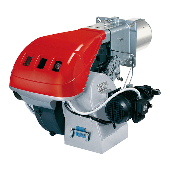
Riello Bio RLS 68/M Installation, Use And Maintenance Instructions
Dual fuel gas oil/ gas burner
Hide thumbs
1
2
Table Of Contents
3
4
5
6
7
8
9
10
11
12
13
14
15
16
17
18
19
20
21
22
23
24
25
26
27
28
29
30
31
32
33
34
35
36
37
38
39
40
41
42
43
44
45
46
47
48
49
50
51
52
53
54
55
56
page
of
56
Go
/
56
Contents
Table of Contents
Bookmarks
Table of Contents
Table of Contents
Declaration
Information and General Warnings
Information about the Instruction Manual
Introduction
General Dangers
Danger: Live Components
Guarantee and Responsibility
Guidance for the Use of Bio Fuel Blends up to 10
Information and General Instructions
Product Disclaimer Statement
Safety and Prevention
Introduction
Safety Warnings
Basic Safety Rules
Personnel Training
Technical Description of the Burner
Burner Designation
Models Available
Technical Data
Electrical Data
Countries of Destination - Burner Categories
Packaging - Weight
Overall Dimensions
Firing Rates
Modulation Ratio
Test Boiler
Commercial Boilers
Burner Description
Standard Equipment
Installation
Notes on Safety for the Installation
Handling
Preliminary Checks
Installer/Servicer Notes for the Use of Gas Oil with Bio Blends up to 10
Operating Position
Boiler Plate
Blast Tube Length
Securing the Burner to the Boiler
Nozzle Installation
Choice of Nozzles for 1St and 2Nd Stage
Nozzle Assembly
Servomotor
Gas Oil Supply
5.11.1 Double-Pipe Circuit
5.11.2 Single-Pipe Circuit
Hydraulic System Layout
Hydraulic Connections
Pump
5.14.1 Technical Data
5.14.2 Pump Priming
Gas Feeding
5.15.1 Gas Feeding Line
Gas Supply
5.16.1 Gas Line
5.16.2 Gas Train Installation
5.16.3 Gas Pressure
Electrical System
Notes on Safety for the Electrical Wiring
Electrical Connections
Calibration of Thermal Relay
Current to the UV Photocell
Start-Up, Calibration and Operation of the Burner
Notes on Safety for the First Start-Up
Adjustment before First Firing (Gas Oil Operation)
Combustion Head Setting
Pump Adjustment
Fan Gate Adjustment
Burner Calibration (Gas Oil Operation)
Firing
Operation
Adjustment before First Firing (Gas Operation)
Burner Starting (Gas Operation)
Burner Firing (Gas Operation)
Burner Calibration (Gas Operation)
First Firing Output
MAX Burner Output
MIN Burner Output
Intermediate Outputs
Air Pressure Switch
Maximum Gas Pressure Switch
Minimum Gas Pressure Switch
Gas Combustion Checks
Burner Operation
Burner Flame Goes out During Operation
Maintenance
Notes on Safety for the Maintenance
Maintenance Programme
Maintenance Frequency
Safety Test - with Gas Feeding Closed
Checking and Cleaning
Safety Components
Opening the Burner
Closing the Burner
Faults - Possible Causes - Solutions
Appendix - Accessories (Optional)
Appendix - Electrical Panel Layout
Advertisement
Quick Links
1
Faults - Possible Causes - Solutions
Download this manual
Installation, use and maintenance instructions
Dual fuel gas oil/ gas burners
GB
Gas progressive two-stage or modulating operation/oil two-stage operation
CODE
20034838 - 20034839
20034840 - 20034841
MODEL
RLS 68/M MX
RLS 120/M MX
TYPE
779 T
780 T
20034985 (5) - 01/2019
Table of
Contents
Previous
Page
Next
Page
1
2
3
4
5
Advertisement
Table of Contents
Need help?
Do you have a question about the Bio RLS 68/M and is the answer not in the manual?
Ask a question
Questions and answers
Related Manuals for Riello Bio RLS 68/M
Burner Riello RLS 300/E Installation, Use And Maintenance Instructions
Dual fuel light oil/ gas burners (60 pages)
Burner Riello RLS 68/E Installation, Use And Maintenance Instructions
Dual fuel light oil/gas burner (48 pages)
Burner Riello RLS 120/E Installation, Use And Maintenance Instructions
Dual fuel light oil/gas burners, progressive two-stage or modulating operation (48 pages)
Burner Riello RLS 650/M MX Installation, Use And Maintenance Instructions
Dual fuel light oil/gas burner progressive two-stage or modulating operation (60 pages)
Burner Riello RLS 310/E MX Installation, Use And Maintenance Instructions
Dual fuel gas oil/ gas burners (96 pages)
Burner Riello RLS 68/EVi MX FS1 Installation, Use And Maintenance Instructions
Dual fuel light oil / gas burners, progressive two-stage or modulating operation (84 pages)
Burner Riello RLS 650/E MX Installation, Use And Maintenance Instructions
Dual fuel light oil/gas burner (56 pages)
Burner Riello RLS 310/M MX Modulating Operation
(76 pages)
Burner Riello RLS 310/EV O2 MX Modulating Operation
Dual fuel light oil/ gas burners (68 pages)
Burner Riello RLS 310/E O2 MX Installation, Use And Maintenance Instructions
Dual fuel gas oil/ gas burners (72 pages)
Burner Riello RLS 300/EV Installation, Use And Maintenance Instructions
Dual fuel light oil/ gas burners (58 pages)
Burner Riello RLS 300/EV FGR Installation, Use And Maintenance Instructions
Dual fuel light oil/ gas burners (64 pages)
Burner Riello C9161400 Installation, Use And Maintenance Instructions
Dual fuel light oil/ gas burners progressive two stage or modulating operation (60 pages)
Burner Riello RLS 68/E MX Installation, Use And Maintenance Instructions
Dual fuel light oil / gas burners (80 pages)
Burner Riello RLS 100 Installation, Use And Maintenance Instructions
Kit for long combustion head (8 pages)
Burner Riello RL Series Installation, Use And Maintenance Instructions
Light oil burners (68 pages)
This manual is also suitable for:
Bio rls 68/mx
Bio rls 120/m
Bio rls 120/mx
20034838
20034839
20034840
...
Show all
20034841
Rls bio 68/m mx
Rls bio 120/m mx
Table of Contents
Print
Rename the bookmark
Delete bookmark?
Delete from my manuals?
Login
Sign In
OR
Sign in with Facebook
Sign in with Google
Upload manual
Upload from disk
Upload from URL


Need help?
Do you have a question about the Bio RLS 68/M and is the answer not in the manual?
Questions and answers