Table of Contents
Advertisement
Quick Links
I
NSTALLATION
Surface Mounted Lift
2311 South Park Rd., Louisville, KY 40219
TOLL FREE: 877-771-5438 FAX: 502-583-5488
IMPORTANT:
, O
& M
PERATION
Two Post
M
EQ10
ODEL
QUALITY LIFTS, LLC
E-mail:
sales@qualitylifts.com
www.qualitylifts.com
READ THIS MANUAL COMPLETELY BEFORE
INSTALLING or OPERATING LIFT
M
AINTENANCE
ANUAL
Rev. 11/30/2020
Advertisement
Table of Contents

Related Manuals for QUALITY LIFTS EQ10


Summary of Contents for QUALITY LIFTS EQ10
- Page 1 & M NSTALLATION PERATION AINTENANCE ANUAL Two Post Surface Mounted Lift EQ10 ODEL QUALITY LIFTS, LLC 2311 South Park Rd., Louisville, KY 40219 TOLL FREE: 877-771-5438 FAX: 502-583-5488 E-mail: sales@qualitylifts.com www.qualitylifts.com IMPORTANT: READ THIS MANUAL COMPLETELY BEFORE INSTALLING or OPERATING LIFT...
-
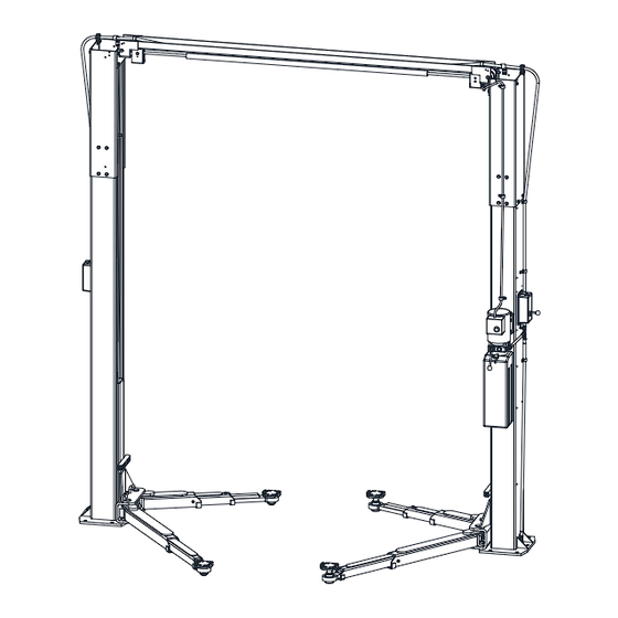
Page 2: General Specifications
Model EQ10 Installation, Operation and Maintenance ENERAL PECIFICATIONS See Figure 1 EQ10 Rise Height (Screw Pads Highest Position) 72 1/4" 75 1/4" (1899 mm) ( (1975 mm) with Adapter) Overall Height 143 7/8" (3655 mm) Overall Width 131 3/4" (3347 mm) Drive-Thru Clearance 98 3/8"... -
Page 3: Vertical Clearance
Model EQ10 Installation, Operation and Maintenance EAD ENTIRE MANUAL BEFORE ASSEMBLING ERTICAL LEARANCE INSTALLING OPERATING OR SERVICING THIS Check the height of the area where the lift is to be EQUIPMENT installed. Clearance should be calculated based on ROPER MAINTENANCE AND INSPECTION IS the full raised height of the lift. -
Page 4: Installation
Model EQ10 Installation, Operation and Maintenance ECEIVING NSTALLATION The shipment should be thoroughly inspected as AFETY EQUIREMENTS FOR NSTALLATION AND soon as it is received. The signed bill of lading is ERVICE acknowledgement by the carrier of receipt in good Refer to ANSI/ALI ALIS (current edition) condition of shipment covered by our invoice. - Page 5 Model EQ10 Installation, Operation and Maintenance NCHORING 4) The anchor bolts must be installed at least 8” from any crack, edge, or expansion joint. 5) Use a concrete hammer drill with a 3/4-inch carbide bit. Tip diameter should conform to ANSI Standard B94.12-1977 (.775 to .787).
- Page 6 Model EQ10 Installation, Operation and Maintenance 23) Beginning on the idler side, attach the idler hose to the cylinder elbow fitting. Route the idler hose (long) up the backside of the column and thru the plastic guide at the top of the extension.
-
Page 7: Single Phase
Model EQ10 Installation, Operation and Maintenance 29) Attach Mechanical Lock Release Cable Assembly to each lock pawl. See Fig 9. Fig. 11 – Arm Install 32) Ensure that the arm restraint gears engage and disengage properly. restraints should disengage when lift is fully lowered. If any... - Page 8 Model EQ10 Installation, Operation and Maintenance IMPORTANT: A sound for these 10 seconds.) Check hydraulic FTER WIRING HAS BEEN COMPLETED & O system for leaks. TEST OPERATION OF OWER VERHEAD IMIT SWITCH HILE RAISING LIFT OPERATE VERHEAD 49) Energize power unit again for 10 seconds. With...
-
Page 9: Wiring Diagram
Model EQ10 Installation, Operation and Maintenance Wiring Diagram FOR SINGLE PHASE ORIGINALLY CONNECTED TO A2 (Normally Open) FIELD CONNECTIONS FIELD CONNECTIONS FOR THREE PHASE FACTORY WIRED FOR 208−240V RECONNECTIONS FOR 440−480V Fig. 13 – Electrical Wiring Diagram Page 9 Rev. 11/30/2020... -
Page 10: Operation Procedure
Model EQ10 Installation, Operation and Maintenance Requirements Operation, Inspection PERATION ROCEDURE Maintenance; and in the case of frame engaging lift, ALI/LP-GUIDE, Vehicle Lifting Points/Quick AFETY OTICES AND ECALS Reference Guide for Frame Engaging Lifts; in a This product is furnished with graphic safety... - Page 11 Model EQ10 Installation, Operation and Maintenance IFTING A EHICLE OWERING EHICLE 1) Ensure that the lifting arms are parked, out to full 1) Ensure that the area under the vehicle is clear of drive thru position. personnel and tools. 2) Center the vehicle between the columns in the 2) Raise the vehicle until both latches are free.
- Page 12 Model EQ10 Installation, Operation and Maintenance AINTENANCE To avoid personal injury, permit only qualified personnel perform maintenance this equipment. Maintenance personnel should follow lockout/tagout instructions per ANSI Z244.1. The following maintenance points are suggested as the basis of a routine maintenance program. The actual maintenance program should be tailored to the installation.
-
Page 13: Parts Breakdown
Model EQ10 Installation, Operation and Maintenance Parts Breakdown Page 13 Rev. 11/30/2020 EQ10-IOM-Q. - Page 14 Model EQ10 Installation, Operation and Maintenance Page 14 Rev. 11/30/2020 EQ10-IOM-Q.
- Page 15 Model EQ10 Installation, Operation and Maintenance Item # Part # Description Item # Part # Qty. Description JSJ5-02-01-00V Power Column Weld L5-06-00CH Lock Release Cable JSJ5-02-01-00FV Idler Column Weld B1140 Lock Pawl JSJ5-02-02-00V Power Column Extension A1132 Lock Spring, 1/2” O.D.
- Page 16 Model EQ10 Installation, Operation and Maintenance REVISIONS 11/30/2020- ADDED STEP TO CHECK THE ARM STOP BOLTS TO MAKE SURE THEY ARE TIGHT. UPDATED LOCK RELEASE CABLE PART NUMBER. Page 16 Rev. 11/30/2020 EQ10-IOM-Q.
Need help?
Do you have a question about the EQ10 and is the answer not in the manual?
Questions and answers