
Related Manuals for Carrier 69NT20-551-300 TO 399


Summary of Contents for Carrier 69NT20-551-300 TO 399
- Page 1 Container Refrigeration OPERATION AND SERVICE 69NT20- -551- -300 TO 399 Container Refrigeration Units T--322 Rev --...
- Page 2 OPERATION AND SERVICE MANUAL CONTAINER REFRIGERATION UNIT MODEL 69NT20-551- -300 TO 399 Streamline Scroll...
- Page 3 SAFETY SUMMARY GENERAL SAFETY NOTICES The following general safety notices supplement the specific warnings and cautions appearing elsewhere in this manual. They are recommended precautions that must be understood and applied during operation and maintenance of the equipment covered herein. The general safety notices are presented in the following three sections labeled: First Aid, Operating Precautions and Maintenance Precautions.
- Page 4 WARNING WARNING Beware of unannounced starting of the evap- Always turn OFF the unit circuit breakers orator and condenser fans. The unit may (CB-1 & CB-2) and disconnect main power cycle the fans and compressor unexpectedly supply before working on moving parts. as control requirements dictate.
- Page 5 CAUTION CAUTION Use only Carrier Transicold approved Polyol When condenser water flow is below 11 lpm Ester Oil (POE) - - Mobil ST32 compressor oil (3 gpm) or when water-cooled operation is not in use, the CFS switch MUST be set to with R-134a.
- Page 6 TABLE OF CONTENTS PARAGRAPH NUMBER Page GENERAL SAFETY NOTICES ............Safety-1 FIRST AID .
- Page 7 TABLE OF CONTENTS (cont) REFRIGERATION CIRCUIT ............2.5.1 Standard Operation .
- Page 8 TABLE OF CONTENTS (cont) OPERATION ................. INSPECTION (Before Starting) .
- Page 9 TABLE OF CONTENTS (cont) SERVICE ..................SECTION LAYOUT .
-
Page 10: Table Of Contents
TABLE OF CONTENTS (cont) 6.21 CONTROLLER ............... 6-13 6.21.1 Handling Modules . - Page 11 LIST OF ILLUSTRATIONS FIGURE NUMBER Page Figure 6-2 Suction Service Valve ............. . . Figure 6-3 Manifold Gauge Set .
- Page 12 LIST OF TABLES TABLE NUMBER Page Table 2-1 Safety and Protective Devices ............Table 3-1 Key Pad Function .
- Page 13 18 and 24 volts, single phase. discharge pressure gauges. The unit is fitted with suction and discharge transducers. The readings may The controller is a Carrier Transicold Micro-Link 3 be viewed on the controller display. microprocessor. controller...
-
Page 14: Controller
1.3.12 460 Volt Cable 1.3.17 Labels Various power cable and plug designs are available for Operating Instruction and Function Code listing labels the main 460 volt supply. The plug options tailor the will differ depending on the options installed. For cables to each customers requirements. -
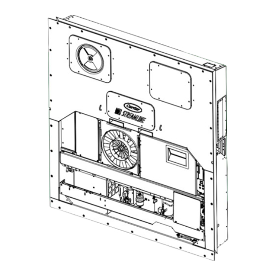
Page 15: Figure 2-1 Refrigeration Unit -- Front Section
SECTION 2 DESCRIPTION 2.1 GENERAL DESCRIPTION valve, suction modulation valve and evaporator coil heaters. The unit model number, serial number and parts identification number can be found on the serial 2.1.1 Refrigeration Unit - - Front Section plate to the left of the economizer. The unit is designed so that the majority of the 2.1.2 Fresh Air Makeup Vent components are accessible from the front, see... -
Page 16: Figure 2-2 Evaporator Section
2.1.3 Evaporator Section The evaporator fans circulate air through the container by pulling it in the top of the unit, directing it through the The evaporator section (Figure 2-2) contains the evaporator coil, where it is heated or cooled, and temperature recorder bulb, return recorder sensor, return discharging it at the bottom. -
Page 17: Figure 2-3 Compressor Section
2.1.4 Compressor Section transducer, discharge temperature sensor and the suction pressure transducers. The compressor section includes the compressor (with high pressure switch) and the oil separator. The supply temperature sensor, supply recorder sensor This section also contains the oil return solenoid, and ambient sensor are located at the left side of the compressor power plug, the discharge pressure compressor. -
Page 18: Figure 2-4 Condenser Section
2.1.5 Air Cooled Condenser Section The condenser fan pulls air in the bottom of the coil and it is discharged horizontally out through the condenser fan grille. The air cooled condenser section (Figure 2-4) consists of the condenser fan, condenser coil, receiver, sight This section also contains the economizer, economizer glass/moisture indicator, liquid line service valve, solenoid valve, economizer expansion valve and the... -
Page 19: Figure 2-5 Control Box Section
2.1.6 Control Box Section 2.1.7 Communications Interface Module The control box (Figure 2-5) includes the manual The communications interface module is a slave operation switches; circuit breaker (CB-1); compressor, module which allow communication with a master fan and heater contactors; control power transformer; central monitoring station. - Page 20 2.2 REFRIGERATION SYSTEM DATA Model RSH105 Weight (Dry) 46.5 kg (103 lb) Approved Oil Mobil ST32 a Compressor/Motor a. Compressor/Motor Oil Charge 2957 ml (100 ounces) Assembly Assembly The oil level range, with the compressor off, should be between the bottom and one-eighth Oil Sight Glass level of the sight glass.
- Page 21 2.3 ELECTRICAL DATA CB-1 Trips at 29 amps CB-2 (50 amp) Trips at 62.5 amps a. Circuit Breaker a. Circuit Breaker CB-2 (70 amp) Trips at 87.5 amps b. Compressor Full Load Amps (FLA) 13 amps @ 460 vac Motor 380 vac, Single Phase, 460 vac, Single Phase, 50 hz...
-
Page 22: Table 2-1 Safety And Protective Devices
PARAGRAPH 2.3 - - Continued Orange wire Power Red wire Output Brown wire Ground Input voltage 5 vdc Output voltage 0 to 3.3 vdc g Humidity Sensor g. Humidity Sensor Output voltage readings verses relative humidity (RH) percentage: 0.99 V 1.65 V 2.31 V 2.97 V... - Page 23 2.5 REFRIGERATION CIRCUIT 2.5.2 Economized Operation 2.5.1 Standard Operation In the economized mode the frozen range and pull down Starting at the compressor, (see Figure 2-6, upper capacity of the unit is increased by subcooling the liquid schematic) the suction gas is compressed to a higher refrigerant entering the evaporator expansion valve.
-
Page 24: Figure 2-6 Refrigeration Circuit Schematic -- Standard Operation
STANDARD OPERATION WITH RECEIVER EVAPORATOR LOW SIDE ACCESS VALVE TXV BULB CONDENSER ECONOMIZER TXV BULB FILTER DRIER DISCHARGE ECONOMIZER SERVICE CONNECTION CPDS OIL SEPARATOR ECONOMIZER SERVICE CONNECTION ECONOMIZER RECEIVER FUSIBLE PLUG SUCTION SERVICE CONNECTION SIGHT GLASS MOISTURE INDICATOR OIL RETURN SERVICE VALVE LIQUID LINE SERVICE... -
Page 25: Figure 2-7 Refrigeration Circuit Schematic -- Economized Operation
EVAPORATOR LOW SIDE ACCESS VALVE TXV BULB CONDENSER ECONOMIZER TXV BULB ECONOMIZER OIL SEPARATOR ECONOMIZER SERVICE ECONOMIZER CONNECTION RECEIVER LIQUID LINE SERVICE CONNECTION LIQUID ECONOMIZER PRESSURE Figure 2-7 Refrigeration Circuit Schematic - - Economized Operation TXV BULB ECONOMIZER TXV BULB OIL SEPARATOR SUCTION SERVICE CONNECTION... -
Page 26: Figure 3- 1 Temperature Control System
SECTION 3 MICROPROCESSOR 3.1 TEMPERATURE CONTROL MICROPRO- operating parameters cargo temperature CESSOR SYSTEM parameters for future retrieval. Coverage of the temperature control software begins with paragraph The temperature control Micro-Link 3 microprocessor 3.2. Coverage of the DataCORDER software is system (see Figure 3- 1) consists of a key pad, display provided in paragraph 3.6. -
Page 27: Figure 3- 2 Key Pad
3.1.1 Key Pad Table 3-1 Key Pad Function The key pad (Figure 3- 2) is mounted on the right-hand FUNCTION side of the control box. The key pad consists of eleven Code Select Accesses function codes. push button switches that act as the user’s interface with the controller. -
Page 28: Figure 3- 4 Control Module
Mounting Screw Fuses Micro-Link 3 Control/DataCORDER Module Control Circuit Power Connection Connectors Software Programming Port Test Points Battery Pack Figure 3- 4 Control Module 3.1.3 Controller b. Provide default independent readouts of set point and supply or return air temperatures. c. - Page 29 a. Press the CODE SELECT key, then press an arrow Defrost interval time is not accumulated in any mode key until the left window displays the desired code until the defrost termination sensor reads less than number. 10_C (50_F). 3.3.3 Failure Action b.
- Page 30 display indicator that economy mode has been Two timers are activated in the dehumidification mode activated. To check for economy mode, perform a to prevent rapid cycling and consequent contactor wear. manual display of code Cd34. They are: 1. Heater debounce timer (three minutes). In order to achieve economy mode, a perishable set point must be selected prior to activation.
- Page 31 and the default reading on the display window will be the The alarm philosophy balances the protection of the return air probe reading. refrigeration unit and that of the refrigerated cargo. The action taken when an error is detected always considers When the return air temperature enters the in-range the survival of the cargo.
- Page 32 (see 3.6.2 DataCORDER Software Figure 3- 1) which may be used with the Carrier The DataCORDER Software is subdivided into the Transicold Data Reader to down load data. A personal Configuration Software, Operational Software and the computer with Carrier Transicold DataView/DataLine Data Memory.
-
Page 33: Table 3-2 Datacorder Configuration Variables
Changing the listed in Table 3-3. configuration to generic and selecting which data points Table 3-3 DataCORDER Standard Configurations to record may be done using the Carrier Transicold Data Retrieval Program. Standard Description Config. -
Page 34: Figure 3- 5 Standard Configuration Download Report
Raw Data Report for ABC1234567 May 31, 2001 to Jun 04, 2001 System Configuration at the Time of Interrogation: Interrogated On Sept 05, 2001 Extracted by DataLine Rev 1.0.0 Controller Software: 5120 Controller Serial #: 04163552 Bill of Lading #: 1 Origin: Origin Date: Destination:... -
Page 35: Figure 3- 6 Data Reader
If a probe alarm is configured to ON, then the associated DataReader alarm is always enabled. The Carrier Transicold Data Reader (see Figure 3- 6) is If the probes are configured to AUTO, they act as a a simple to operate hand held device designed to extract group. - Page 36 In response to the demand to replace fumigation with this environmentally sound process, Carrier has e. To initiate USDA Recording, connect the personal integrated...
-
Page 37: Table 3-4 Controller Configuration Variables
To display alarm codes: 3.6.14 ISO Trip Header a. While in the Default Display mode, press the ALT. DataLine provides the user with an interface to MODE & ALARM LIST keys. This accesses the Data- view/modify current settings of the ISO trip header CORDER Alarm List Display Mode, which displays through the ISO Trip Header screen. -
Page 38: Table 3-5 Controller Function Codes
Table 3-5 Controller Function Codes (Sheet 1 of 3) Code TITLE DESCRIPTION Note: If the function is not applicable, the display will read “-- -- -- -- -- ” Display Only Functions Displays the SMV percent open. The right display reads 100% when the valve is Cd01 Suction Modulation fully open. - Page 39 Table 3-5 Controller Function Codes (Sheet 2 of 3) Configurable Functions NOTE Function codes Cd27 through Cd37 are user-selectable functions. The operator can change the value of these functions to meet the operational needs of the container. There are two modes for defrost initiation, either user--selected timed intervals or automatic control.
- Page 40 Table 3-5 Controller Function Codes (Sheet 3 of 3) Relative humidity set point is available only on units configured for dehumidifica- tion. When the mode is activated, the control probe LED flashes on and off every second to alert the user. If not configured, the mode is permanently deactivated and “-- -- -- -- -- ”...
-
Page 41: Table 3-6 Controller Alarm Indications
Table 3-6 Controller Alarm Indications (Sheet 1 of 4) Code TITLE DESCRIPTION Alarm 14 is triggered if the electronic phase detection system is unable to deter- mine the correct phase relationship. DIRCHECK will be displayed while the rela- tionship is determined. If the system is unable to determine the proper relation- AL14 Phase Sequence ship alarm 14 will remain active. - Page 42 Table 3-6 Controller Alarm Indications (Sheet 2 of 4) Alarm 25 is triggered by the opening of the condenser motor internal protector and will disable all control units except for the evaporator fans. This alarm will AL25 Condenser Fan Mo- remain active until the motor protector resets.
- Page 43 Table 3-6 Controller Alarm Indications (Sheet 3 of 4) Alarm 56 is activated by an invalid primary return temperature sensor reading that is outside the range of --50 to +70_C (--58_F to +158_F). If Alarm 56 is acti- vated and the primary return is the control sensor, the secondary return sensor will be used for control if the unit is so equipped.
- Page 44 Table 3-6 Controller Alarm Indications (Sheet 4 of 4) NOTE If the Controller is configured for four probes without a DataCORDER, the DataCORDER alarms AL70 and AL71 will be processed as Controller alarms AL70 and AL71. Refer to Table 3-10, page 3-26. The Controller performs self-check routines.
-
Page 45: Table 3-7 Controller Pre-Trip Test Codes
Table 3-7 Controller Pre-Trip Test Codes (Sheet 1 of 4) Code TITLE DESCRIPTION NOTE “Auto” or “Auto1” menu includes the: P0, P1, P2, P3, P4, P5, P6 and rSLts. “Auto2” menu in- cludes P0, P1, P2, P3, P4, P5, P6, P7, P8, P9, P10 and rSLts. All lights and display segments will be energized for five seconds at the start of P0--0 Pre-Trip Initiated... -
Page 46: Table 3-7 Controller Pre-Trip Test Codes
Table 3-7 Controller Pre-Trip Test Codes (Sheet 2 of 4) Requirements: For units equipped with secondary supply probe only. Pass/Fail Criteria: The temperature difference between primary and secondary probe (supply) is compared. P5-1 Supply Probe Test NOTE If this test fails, “P5-1” and FAIL will be displayed. If both Probe tests (this and the SUPPLY/ RETURN TEST) pass, because of the multiple tests, the display will read ’P 5’... -
Page 47: Table 3-7 Temperature Controller Pre-Trip Test Codes
Table 3-7 Temperature Controller Pre-Trip Test Codes (Sheet 3 of 4) NOTE P7--0 & P8 are included with “Auto2 & Auto 3” only. P9--0 through P10 are included with “Auto2” only NOTE This test is skipped if the sensed ambient temperature is less than 7_C (45_F), the return air temperature is less than --17.8_C (0_F), the water P7-0 High Pressure... -
Page 48: Table 3-7 Controller Pre-Trip Test Codes (Sheet 4 Of 4)
Table 3-7 Controller Pre-Trip Test Codes (Sheet 4 of 4) Setup: If the container temperature is below 7.2_C (45_F), the set point is changed to 7.2_C and a 180 minute timer is started. The control will then be placed in the equivalent of normal heating. If the container temperature is above 7.2_C at the start of the test, then the test proceeds immediately to test 10--1. -
Page 49: Table 3-8 Datacorder Function Code Assignments
Table 3-8 DataCORDER Function Code Assignments NOTE Inapplicable Functions Display “-- -- -- -- -- ” To Access: Press ALT. MODE key Code TITLE DESCRIPTION Recorder Supply Current reading of the supply recorder sensor. Temperature Recorder Return Current reading of the return recorder sensor. Temperature USDA 1,2,3 Temper- dC3-5... -
Page 50: Table 3-9 Datacorder Pre-Trip Result Records
Table 3-9 DataCORDER Pre-Trip Result Records Test TITLE DATA Heater On Pass/Fail/Skip Result, Change in current for Phase A, B and C Heater Off Pass/Fail/Skip Result, Change in currents for Phase A, B and C Pass/Fail/Skip Result, Water pressure switch (WPS) -- Open/Closed, Condenser Fan On Change in currents for Phase A, B and C Condenser Fan Off... -
Page 51: Table 3-10 Datacorder Alarm Indications
Table 3-10 DataCORDER Alarm Indications To Access: Press ALT. MODE key Code No. TITLE DESCRIPTION The supply recorder sensor reading is outside of the range of --50_C to 70_C (--58_F to +158_F) or, the probe check logic has determined there is a fault with this sensor. -
Page 52: Figure 4-1 Make Up Air Flow Chart
SECTION 4 OPERATION 4.1 INSPECTION (Before Starting) 4.3 ADJUST FRESH AIR MAKEUP VENT WARNING The purpose of the fresh air makeup vent is to provide ventilation for commodities that require fresh air circulation. The vent must be closed when transporting Beware of unannounced starting of the frozen foods. - Page 53 4.4 CONNECT REMOTE MONITORING c. Install new chart making sure chart is under the four RECEPTACLE corner tabs. Lower the stylus until it has made contact with the chart. Close and secure door. If remote monitoring is required, connect remote DataCORDER monitor plug at unit receptacle.
- Page 54 NOTE c. TO RUN AN INDIVIDUAL TEST: Scroll through the selections by pressing the UP ARROW or DOWN 1. Prior to starting tests, verify that unit ARROW keys to display an individual test code. voltage (Function Code Cd 07) is within Pressing ENTER when the desired test code is dis- tolerance unit...
-
Page 55: Figure 4-2 Controller Operation -- Perishable Mode
c.The 30 minute timer will be reset at each of the follow- Any probe(s) determined to be outside the limits will ing conditions: cause the appropriate alarm code(s) to be displayed to identify which probe(s) needs to be replaced. The P5 1. -
Page 56: Figure 4-4 Perishable Mode
FALLING RISING TEMPERATURE TEMPERATURE START UNLOADED, TRANSITION TO COOLING ECONOMIZED ECONOMIZED OPERATION +.20_C SET POINT - -0.20_C AIR CIRCULATION AIR CIRCULATION NOTE: TEMPERATURES INDICATIONS ARE ABOVE OR BELOW SET POINT Figure 4-3 Controller Operation - - Frozen Mode will switch operation from compressor contactor PB to ENERGIZED DE- -ENERGIZED compressor contactor PA. -
Page 57: Figure 4-5 Perishable Mode Heating
records the supply air temperature, set point and ing with the condenser fan motor (CF), compressor time. A calculation is then performed to determine motor (CH), economizer solenoid valve (ESV), low temperature drift from set point over time. speed evaporator fan motors (ES) energized and the COOL light illuminated. -
Page 58: Figure 4-7 Defrost
Manual Defrost/Interval key operation: If the controller is programmed with the Lower DTT setting option the defrost termination thermostat set Depressing and holding the Defrost Interval key for point may be configured to the default of 25.6_C (78_F) five (5) seconds will initiate defrost. If the defrost in- or lowered to 18_C (64_F). - Page 59 SECTION 5 TROUBLESHOOTING REMEDY/ REFERENCE CONDITION POSSIBLE CAUSE SECTION 5.1 UNIT WILL NOT START OR STARTS THEN STOPS External power source OFF Turn on Start-Stop switch OFF or defective Check No power to unit No power to unit Circuit breaker tripped or OFF Check Circuit breaker OFF or defective Check...
- Page 60 REMEDY/ REFERENCE CONDITION POSSIBLE CAUSE SECTION 5.3 UNIT RUNS BUT HAS INSUFFICIENT COOLING Abnormal pressures Abnormal temperatures 5.15 Abnormal currents 5.16 Controller malfunction Evaporator fan or motor defective 6.17 Shortage of refrigerant 6.7.1 Refrigeration System Suction modulation valve lost track of step count Power cycle Suction modulation valve malfunction 6.20...
- Page 61 REMEDY/ REFERENCE CONDITION POSSIBLE CAUSE SECTION 5.6 UNIT WILL NOT DEFROST PROPERLY - - Continued Manual defrost switch defective Replace Will not initiate defrost Will not initiate defrost manually Defrost temperature sensor open 4.9.5 Initiates but relay (DR) drops Low line voltage Heater contactor or coil defective Replace Initiates but does not defrost...
- Page 62 REMEDY/ REFERENCE CONDITION POSSIBLE CAUSE SECTION 5.9 CONTROLLER MALFUNCTION Defective Sensor 6.22 Defective wiring Check Fuse (F1, F2, F3) blown Replace Will not control Will not control Stepper motor suction modulation valve circuit malfunction 6.20 Low refrigerant charge 5.10 NO EVAPORATOR AIR FLOW OR RESTRICTED AIR FLOW Frost on coil Evaporator coil blocked Evaporator coil blocked...
- Page 63 REMEDY/ REFERENCE CONDITION POSSIBLE CAUSE SECTION 5.14 COMPRESSOR OPERATING IN REVERSE CAUTION Allowing the scroll compressor to operate in reverse for more than two minutes will result in internal compressor damage. Turn the start- -stop switch OFF immediately. Incorrect wiring of compressor Incorrect wiring of compressor contactor(s) Electrical Electrical...
-
Page 64: Figure 6-1 Service Valve
SECTION 6 SERVICE NOTE To avoid damage to the earth’s ozone layer, use a refrigerant recovery system whenever removing refriger- ant. When working with refrigerants you must comply with all local government environmental laws. In the U.S.A., refer to EPA section 608. WARNING Never use air for leak testing. -
Page 65: Figure 6-3 Manifold Gauge Set
The manifold 5. Repeat the procedure to connect the other side of gauge/hose set is available from Carrier Transicold. the gauge set. (Carrier Transicold P/N 07-00294-00, which includes items 1 through 6, Figure 6-4.) To perform service using... -
Page 66: Figure 6-5. Refrigeration System Service Connections
(8 m /hr = 5 cfm WARNING volume displacement) and an electronic vacuum gauge. (The pump is available from Carrier Trans- icold, P/N 07-00176-11.) Never use air for leak testing. It has been c. If possible, keep the ambient temperature above determined that pressurized, air-rich mix- 15.6_C (60_F) to speed evaporation of moisture. -
Page 67: Figure 6-6. Compressor Service Connections
6.6.3 Procedure - Complete system a. Remove all refrigerant using a refrigerant recovery system. b. The recommended method to evacuate and dehy- drate the system is to connect evacuation hoses at the compressor suction, compressor economizer and liquid line service valve (see Figure 6-5). Be sure the service hoses are suited for evacuation purposes. -
Page 68: Table 6-1 Compressor Kit
d. On units equipped with a receiver, the level should be CAUTION between the glasses. On units equipped with a water cooled condenser, the level should be at the center of the glass. If the refrigerant level is not correct, contin- The scroll compressor achieves low suc- ue with the following paragraphs to add or remove re- tion pressure very quickly. -
Page 69: Figure 6-7 Compressor Upper Mounting
Plug the Use only Carrier Transicold approved top of the replacement compressor sight glass with the plug (kit item 5) to prevent spilling oil. -
Page 70: Figure 6-9 High Pressure Switch Testing
3 Check the controller function code Cd1 for the suc- 6.10.2 Checking High Pressure Switch tion modulation valve (SMV) position. It should be at least 20% open. WARNING 4 Locate the oil sight glass on the side of the compres- sor (item 7, Figure 2-3). -
Page 71: Figure 6-10 Thermostatic Expansion Valve Bulb
c. Unsolder discharge line and remove the line to the 2. Check the moisture-liquid indicator if the indicator receiver or water-cooled condenser. shows a high level of moisture, the filter-drier should be replaced. d. Remove coil mounting hardware and remove the coil. b. -
Page 72: Figure 6-11 Evaporator Expansion Valve
the evaporator outlet test pressures at the suction modulation valve. g. Subtract the saturation temperatures determined in step f. from the temperatures measured in step e.. The difference is the superheat of the suction gas. INLET Determine the average superheat It should be 4.5 to 6.7 °C (8 to 12 °F) 6.14.2 Valve Replacement a. -
Page 73: Figure 6-14. Unloader Solenoid Valve
6.15 EVAPORATOR COIL AND HEATER Replacing Valve Internal Parts (Unloader ASSEMBLY Solenoid Only) 1 Pump down the unit. Refer to paragraph 6.4. The evaporator section, including the coil, should be cleaned regularly. The preferred cleaning fluid is fresh 2 Be sure electrical power is removed from the unit. water or steam. -
Page 74: Figure 6-15. Oil Return Solenoid Valve (Orv), Economizer Solenoid Valve (Esv)
Replace access panel making sure that panel does not leak. Lock--wire the T.I.R. locking device(s). Slotted Screw Washer Coil Enclosing Tube and Body Figure 6-15. Oil Return Solenoid Valve (ORV), Economizer Solenoid Valve (ESV), Liquid Injection Solenoid Valve (LIV) 1. Bracket 6. - Page 75 automatically terminated and the valves return to WARNING normal machinery control. To operate the override, do the following: With power OFF discharge the capacitor a. Press the CODE SELECT key then press an AR- before disconnecting the circuit wiring. ROW key until Cd41 is displayed in the left window. The right window will display a controller communica- 6.18.3 Checking The Capacitor tions code.
-
Page 76: Handling Modules
Checking with SMA-12 portable stepper drive tester The guidelines and cautions provided herein should be The SMA-12 portable stepper drive tester (Carrier followed when handling modules. These... -
Page 77: Controller Trouble-Shooting
Figure 6-18 Controller Section of the Control Box This test point enables the user to check if the heat a. Obtain a grounding wrist strap (Carrier Transicold termination thermostat (HTT) contact is open or closed. part number 07--00--304--00)and a static dissipation mat (Carrier Transicold part number 07--00304--00. -
Page 78: Removing And Installing A Module
6. Press the ENTER key on the keypad. 6.21.4 Removing and Installing a Module a. Removal: 7. The Display will show the message “Pro SoFt.” This message will last for up to one minute. 1. Disconnect all front wire harness connectors and move wiring out of way. -
Page 79: Sensor Replacement
e. Using the plug connector marked “EC”, that is con- c. Cut one wire of existing cable 40 mm (1-1/2 inch) nected to the back of the controller, locate the sensor shorter than the other wire. wires (RRS, RTS, SRS, STS, AMBS, DTS, CPDS d. -
Page 80: Sensor Re--Installation
T.I.R. Bolts Supply STS probe Stream Insulation SRS probe Back Panel Supply Sensor Mounting Clamp Sensor Wires Gasketed Gasket Cover Mounting Plate Gasketed 2.5” Drip Loop Support Plate Figure 6-21 Supply Sensor Positioning 6.22.3 Sensor Re- -Installation c Sensor DTS The DTS sensor must have insulating material placed a. - Page 81 If the optional DataCORDER battery pack is being used, d. Install a new chart, make sure the chart center hole and the charge is too low to enable recording during the is placed over the center hub, and the chart edges power off period of less than thirty days, the pen tip will are behind the four hold down tabs (item 9).
-
Page 82: Electronic Partlow Temperature Recorder
12-00464-xx Where xx= an even number (example: 12- -00464- -08) This procedure provides instructions for repair of the Carrier Transicold composite control box. Damage to NOTE the control box may be in the form of a chip or hole, a crack, a damaged thread insert or damage to the door Use chart CTD P/N 09-00128-00 (°F) -
Page 83: Chips And Holes
The material can be cut to suit and riveted in place. An adhesive sealant must be used to make the repair watertight. The adhesive sealant (Sikaflex 221) is included in Crack Repair Kit Carrier Transicold part number... -
Page 84: Table 6-3 Crack, Chip & Hole Repair Kit
Static Mixing Tube (Loctite 983440) 07--00390--00 . . . Instruction Sheet 98--02338--00 Note: Insert repair procedures require use of an Application Gun, Carrier part number 07--00391--00 Table 6-5 Drill Information Item Insert part number Drill size and depth 34- 06231- 01 10.3 mm x 17.8 mm deep (.404 in. -
Page 85: Figure 6-25. Insert Location
Figure 6-25. Insert Location T-322 6-22... -
Page 86: Communications Interface Module Installation
6.26 COMMUNICATIONS INTERFACE MODULE c.. Remove the circuit breaker panel, with circuit INSTALLATION breaker, from the control box. d.. Locate, wires CB21/CIA3, CB22/CIA5 CB23/CIA7 that have been tied back in the wire harness. Remove the protective heat shrink from the ends of the wires. e.. -
Page 87: Table 6-7 R-134A Temperature - Pressure Chart
Table 6-7 R-134a Temperature - Pressure Chart Temperature Vacuum Temperature Pressure _ _ _ _ F _ _ _ _ C “/hg cm/hg kg/cm@ @ @ @ _ _ _ _ F _ _ _ _ C psig kg/cm@ @ @ @ --40 --40 14.6... -
Page 88: Introduction
SECTION 7 ELECTRICAL WIRING SCHEMATICS 7.1 INTRODUCTION This section contains the Electrical Schematics and Wiring Diagrams. The diagrams are presented as follows: Figure 7-1 Provides the legend for use with all figures. Figure 7-2 Provides the basic schematic diagram. Figure 7-3 Provides the schematic and wiring diagrams for the Electronic Partlow Recorder Figure 7-4 Provides the basic wiring diagram. -
Page 89: Figure 7-2 Schematic Diagram
Figure 7-2 SCHEMATIC DIAGRAM T-322... -
Page 90: Figure 7-3 Schematic Diagram, Wiring Diagram-- Electronic Partlow Recorder
NOTE: STANDARD CONTROLLER JUMPERS: MA3 TO MA7 AND MA9 TO MA11 (SEE Figure 7-2 ) ARE REMOVED IN THIS APPLICATION NOTE: STANDARD CONTROLLER JUMPERS: MA3 TO MA7 AND MA9 TO MA11 (SEE Figure 7-2) ARE REMOVED IN THIS APPLICATION Figure 7-3 SCHEMATIC DIAGRAM, WIRING DIAGRAM- - Electronic Partlow Recorder T-322... -
Page 91: Figure 7-4 Wiring Diagram
Figure 7-4 WIRING DIAGRAM (Sheet 1 of 2) T-322... - Page 92 Figure 7-4 WIRING DIAGRAM (Sheet 2 of 2) T-322...
- Page 93 INDEX Evaporator, 6-10 Evaporator Fan, 1-2, 6-11 Air Cooled Condenser Section, 2-4 Evaporator Section, 2-2 Alarm, 3-6, 3-10, 3-11, 3-12, 3-16, 3-26 Expansion Valves, 6-8 Battery, 1-1 Failure Action, 3-4 Filter--Drier, 6-8 Fresh Air Makeup, 2-1, 4-1 Frozen Mode, 4-6 Capacitors, 6-11 Frozen Mode -- Conventional, 3-6 Checking Superheat, 6-8...
- Page 94 INDEX Manifold Gauge Set, 6-1 Safety and Protective Devices, 2-8 Microporcessor System, 3-1 Sampling Type, 3-10 Modes Of Operation, 3-4 Sensor Configuration, 3-8 Sequence Of Operation, 4-4 Service Valves, 6-1 Solenoid Valves, 6-10 Oil, 6-6 Starting, 4-2 Operational Software, 3-3, 3-7 Stopping, 4-2 Option Descriptions, 1-1 Suction Modulating Valve, 6-13...
- Page 95 Carrier Transicold Division, Carrier Corporation Container Products Group P.O. Box 4805 Syracuse, N.Y. 13221 U.S A www.carrier.transicold.com A member of the United Technologies Corporation family. Stock symbol UTX ã2004 Carrier Corporation D Printed in U. S. A. 08/04...
Need help?
Do you have a question about the 69NT20-551-300 TO 399 and is the answer not in the manual?
Questions and answers