
Subscribe to Our Youtube Channel
Related Manuals for Digital Equipment DECbridge 90FL


Summary of Contents for Digital Equipment DECbridge 90FL
- Page 1 DECbridge 90FL Owner’s Manual Order Number: EK-DEWGF-OM. A01 Revision/Update Information: This is a new manual. Digital Equipment Corporation Maynard, Massachusetts...
- Page 2 First Edition, August 1992 The information in this document is subject to change without notice and should not be construed as a commitment by Digital Equipment Corporation. Digital Equipment Corporation assumes no responsibility for any errors that may appear in this document.
-
Page 3: Table Of Contents
3–11 4 Managing the DECbridge 90FL DECbridge 90FL Operation ......4–1 DECbridge 90FL Functions . - Page 4 Digital Personnel ....... . B–2 Index Figures Sample DECbridge 90FL Connection ....1–1 1–3 1–2 Indicators and Connectors .
- Page 5 Protocol Type Codes and Names ....4–17 DECbridge 90FL Error Messages ....4–4 4–20...
-
Page 7: About This Manual
DECbridge 90FL. This manual also provides the specifications and lists the related documentation for the DECbridge 90FL. In this manual, the DECbridge 90FL unit may be referred to as the DECbridge 90FL, work group bridge, bridge, or WGB. Organization This manual has five chapters, two appendices, and an index. - Page 8 Conventions This manual uses the following conventions: Convention Meaning Note Provides general information boldface type Boldface type in examples indicates user input. For example: DECbridge> SET PROTOCOL parameters Parameters are italicized. For example: SHOW PORT slot number Characters within brackets represent optional parameters. For example: SHOW PORT [hub number, slot number] viii...
-
Page 9: Overview
The DECbridge 90FL unit offers a reliable, high-performance, easy-to-install means of connecting two local area networks (LANs). Configured as a standalone unit or in the DEChub 90 backplane, the DECbridge 90FL provides greater network reliability and efficiency by allowing the local area network to be partitioned into a number of smaller LANs. - Page 10 When the work group consists of fewer than 200 stations, the DECbridge 90FL automatically prevents unnecessary traffic from being transmitted from one LAN to the other. When there are more than 200 stations in the work group, the DECbridge 90FL enters flood mode, which reduces the effectiveness of the traffic isolation, but ensures full connectivity across the bridge.
-
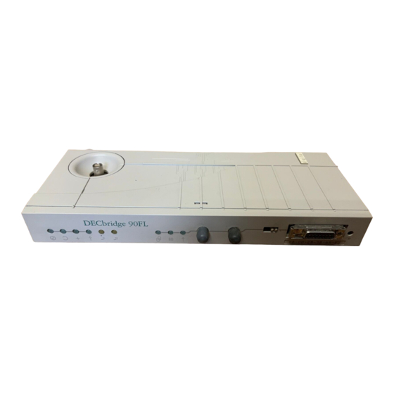
Page 11: Decbridge 90Fl Front Panel Lights And Switches
(Figure 1–2). The lights (LEDs) indicate the status of the DECbridge 90FL. One of the switches is a two-way switch that is used to select either the fiber-optic or AUI port for connection to the backbone; the other switch is used to reset the DECbridge 90FL password. -
Page 12: Indicators And Connectors
Figure 1–2 shows the DECbridge 90FL indicators and connectors. Figure 1–2 Indicators and Connectors L J - 0 2 0 7 4 - T I 0 DC OK Indicator - (Green) Turns on when power supply is providing power to the bridge. - Page 13 Backbone Port AUI Connector - Provides AUI connection to the backbone port of the DECbridge 90FL. Password Reset Switch - Nullifies the password for the DECbridge 90FL. The bridge is accessible without a password until a new password is defined.
- Page 14 Backplane Connector - Provides work group network connection to the DECbridge 90FL when it is installed in the DEChub backplane. Power Connector - Provides +5.0 and +12.0 V from the DECbridge 90FL power supply (standalone) or the DEChub 90 power supply (mounted).
-
Page 15: Configuring The Decbridge 90Fl
The DECbridge 90FL unit has several configuration rules and guidelines that must be followed during installation and use. Each LAN connected by the DECbridge 90FL is required to be an Ethernet or IEEE 802.3 compliant CSMA/CD LAN. The backbone port of the DECbridge 90FL provides both fiber-optic (10Base-FL) and AUI (10Base5) connections, as shown... -
Page 16: Decbridge 90Fl Configured To Fiber-Optic Backbone
Figure 2–1 DECbridge 90FL Configured to Fiber-Optic Backbone 50-OHM 50-OHM Terminator Terminator System System Rx Tx Rx Tx Rx Tx 50-OHM Terminator Backbone Port Work F/O Connection Group Bridge 50-OHM Terminator System System System L J - 0 2 0 7 5 - T I 0... -
Page 17: Decbridge 90Fl Configured To Aui Backbone
Figure 2–2 shows the DECbridge 90FL configured to an AUI backbone. Figure 2–2 DECbridge 90FL Configured to AUI Backbone Sy stem Syst em 50- OHM 50-O HM Terminator Te rmi na t or Tra ns ceiv er H400 5 Transce i ver... -
Page 18: Supported Configurations
To avoid enabling flood mode when a work group consists of more than 200 stations, separate the work group into smaller groups of less than 200 stations each with its own DECbridge 90FL. Figure 2–3 shows a configuration for a work group with more than 200 stations. -
Page 19: Work Group With More Than 200 Stations
• Redundant connections to the backbone If two DECbridge 90FL units are configured into a redundant connection to the backbone, the spanning tree algorithm will allow only one bridge to forward traffic at a time. However, if a failure occurs in the backbone that causes the connection to be separated into two LANs, the spanning tree may reconfigure to pass all backbone traffic through your work group. - Page 20 • Bridges in the work group If there are additional bridges on the work group side of the DECbridge 90FL, be sure to count the stations on all LANs in the work group against the 200- station limit and count each bridge as two against the total. In addition, if...
-
Page 21: Bridges In The Work Group
This guideline for networks with typical packet traffic loading is a compromise of the many different protocols offered and used on Ethernet and IEEE 802.3 LANs. Figure 2–6 shows multiple bridges in the work group. Configuring the DECbridge 90FL 2–7... -
Page 22: Multiple Bridges In Work Group
Mor e t ha n s ev e n br i dge s bet w ee n s t a t i on s o n t h e Ne two r k. L J - 0 2 2 3 6 - T I 0 2–8 Configuring the DECbridge 90FL... -
Page 23: Installation
These requirements are provided in Table A–2 in Appendix A. To install the DECbridge 90FL on a desk top or table, make sure that the air circulation around the DECbridge 90FL does not become obstructed by papers or other materials. -
Page 24: Standalone Installation
When you choose a location, make sure that the power supply can be placed within 1.8 meters (6 feet) of the DECbridge 90FL and that the distance from the power supply to the ac outlet does not exceed 2.4 meters (8 feet). - Page 25 Figure 3–1 Standalone Installation 50- OHM Ter m inato r T- Co nnect or Power Symbol Fiber-optic Backbone Connectors Backbone Selector Switch L J - 0 2 0 7 9 - T I 0 Installation 3–3...
-
Page 26: Mount The Decbridge 90Fl On A Wall
Mount the DECbridge 90FL on a Wall To install the DECbridge 90FL as a standalone wall-mount unit, perform the following procedure and refer to Figure 3–1 and Figure 3–2. 1. Remove the back cover of the DECbridge 90FL (Figure 3–2). -
Page 27: Removing The
Figure 3–2 Removing the Back Cover L J - 0 0 3 2 0 - T I 0 Installation 3–5... -
Page 28: Make Connections For Standalone Installations
When the AUI port is attached to a 10Broad36 modem, the modem should be configured for local echo of transmissions. Note The DECbridge 90FL does not detect a collision presence test failure in the transceiver that is connected to the AUI port. Figure 3–3 shows the proper connection of the transceiver cable. -
Page 29: Connecting Transceiver Cables
DECbridge 90FL. To prevent damage to the cables, attach the pair of fiber-optic cables to the DECbridge 90FL, without making sharp bends or kinks. 2. Insert the fiber-optic cable into the connector until it stops. Installation 3–7... -
Page 30: Connecting To The Middle Of A Thinwire Segment
Work Group Connection Connect the work group by attaching a segment of ThinWire cable to the ThinWire connector on the DECbridge 90FL. When connecting to a ThinWire cable, make sure that the cables are properly terminated (Figure 3–4 and Figure 3–5). -
Page 31: Backplane Installation
To install the DECbridge 90FL in the DEChub 90 backplane, use the DECbridge 90FL kit, order number DEWGF-MA. The kit contents are listed in Appendix A. To install the DECbridge 90FL in the DEChub 90 backplane, refer to Figure 3–6 and follow these procedures: Insert the DECbridge 90FL into the DEChub 90 Backplane 1. -
Page 32: Installing The Decbridge 90Fl In Dechub 90 Backplane
Figure 3–6 Installing the DECbridge 90FL in DEChub 90 Backplane L J - 0 2 1 5 6 - T I 0 3. Rock the bridge into place. You will hear a click when the bridge is secured in the slot. -
Page 33: Make Connections For Backplane Installations
3. Power up the backplane if power is not already on. The DECbridge 90FL will run a 10-second self-test during which all front panel lights will turn on. (The exception to this is the Link Monitor Light; it will be on only if you have a good fiber-optic link at the time of power up.) -
Page 35: Managing The Decbridge 90Fl
DECbridge 90FL Operation The DECbridge 90FL is a packet store-and-forward device that receives all IEEE 802.3 and Ethernet packets and, if necessary, forwards them from one port to the other. This capability enables the bridge to isolate high-traffic areas from the rest of the LAN. -
Page 36: Decbridge 90Fl Functions
IEEE 802.3 and Ethernet compliance requirements. • Connectivity - The DECbridge 90FL can be used on both IEEE 802.3 and Ethernet networks. • Backbone connection - The DECbridge 90FL provides switch-selectable AUI or fiber-optic connection to the backbone. -
Page 37: Spanning Tree Algorithm
• Automatic self-test - The DECbridge 90FL automatically initiates a 10-second self-test of the basic functions of the DECbridge 90FL when the bridge is powered up. • Online diagnostics - The DECbridge 90FL has automated continuous testing of the DECbridge 90FL hardware. -
Page 38: Mop Functions
A VMS system may have more than one Ethernet interface; therefore, the circuit name is needed. The Ethernet address can be found on the label on the DECbridge 90FL front panel. The following Ethernet circuit names, based on system type, apply:... -
Page 39: Ethernet Circuit Names For Systems
(where the Ethernet circuit name is bna-0), you can use the following commands: $ NCP NCP> DEFINE NODE DBRG1 ADDRESS 13.87 HARDWARE 08-00-2b-01-23-45 - SERVICE CIR BNA-0 NCP> SET NODE DBRG1 ALL You can then enter the following: $ NCP CONNECT NODE DBRG1 Managing the DECbridge 90FL 4–5... -
Page 40: Accessing Mop From Ultrix Systems
Console connected (press CTRL/D when finished) Console Carrier User Interface The DECbridge 90FL is not shipped with a pre-set password; therefore, no password prompt appears when you connect for the first time. For secure operation of the DECbridge 90FL, you should define a password using the DEFINE BRIDGE PASSWORD command. -
Page 41: Console Carrier Command Language
The command options are: DEFINE DISPLAY LIST SHOW TEST (for manufacturing use only) Table 4–2 provides a summary of the DECbridge 90FL commands. Table 4–2 Summary of DECbridge 90FL Commands Command Argument and Parameter DEFINE BRIDGE AGE age BRIDGE FLOOD... - Page 42 Table 4–2 (Cont.) Summary of DECbridge 90FL Commands Command Argument and Parameter PORT port number ENABLE DISABLE PROTOCOL protocol number FILTER ALL protocol identifier FILTER BACKBONE protocol identifier FILTER GROUP protocol identifier FILTER WORKGROUP protocol identifier FORWARD protocol identifier NONE...
-
Page 43: Description Of Command Parameters
A protocol number is a decimal index into the protocol database. The valid range is 1 to 16. A port number is either a DECbridge 90FL port, or the number of a port on a repeater installed in the DEChub backplane with the bridge. The DECbridge backbone port is the single digit 1. -
Page 44: Description Of Commands
DEFINE BRIDGE FLOOD DISABLE SET BRIDGE FLOOD DISABLE Disables flood mode in the DECbridge 90FL. Attempting to disable flood mode with a work group larger than 200 stations (that is, when the Work Group Size Exceeded light is on) will not be successful. - Page 45 DEFINE BRIDGE FLOOD ENABLE SET BRIDGE FLOOD ENABLE Enables flood mode in the bridge. Refer to the DECbridge 90FL Operation section and the previous flood commands for a description of flood mode. DEFINE BRIDGE HUB_MANAGEMENT DISABLE SET BRIDGE HUB_MANAGEMENT DISABLE Disables all repeater management through the DECbridge 90FL unit for DECrepeater 90 units in the DEChub 90 backplane.
- Page 46 Disables the use of the bridge spanning tree autoconfiguration algorithm for your DECbridge 90FL unit and prevents forwarding of any spanning tree network messages. If spanning tree is disabled, the DECbridge 90FL will not detect loops in the network bridge topology. If a loop is configured while the spanning tree algorithm is disabled, the network will be quickly saturated by the forwarding of messages around this loop.
- Page 47 Use the SET PROTOCOL NONE command to delete protocol filters. Generally, use the SET PROTOCOL FILTER ALL command to stop unwanted protocols rather than to list explicitly the permitted protocols. Managing the DECbridge 90FL 4–13...
- Page 48 Displays the nonvolatile bridge-wide parameters. LIST PROTOCOL protocol number[, protocol number] Shows either "unused," or the protocol type value, for every entry in the nonvolatile protocol database. This filter becomes the active filter when the DECbridge 90FL is reset. 4–14 Managing the DECbridge 90FL...
- Page 49 If indexes are omitted, the addresses of all stations in the work group are listed. When the DECbridge 90FL is used with repeaters, the hub slot number and repeater port to which each station is attached are also displayed.
- Page 50 Displays all the MOP counters, bridge counters, and spanning tree state kept by the DECbridge 90FL. Port 1 is the backbone port; port 2 is the work group port. The spanning tree port states are listed in the following table:...
-
Page 51: Protocol Filtering Examples
Numbers range from 1 to 16. If numbers are omitted in the command, all 16 protocol filters are displayed. The LIST command shows the filters that are loaded when the DECbridge 90FL is reset. SHOW REPEATER [[hub slot number,] slot number] Shows the type of repeater and the port status for each port on that repeater. - Page 52 Example 1: Keeping VAXcluster traffic out of your work group. If you have an entire Local Area VAXcluster (LAVc) on the work group side of the DECbridge 90FL, you can define the filtering with the following command: DECbridge> DEFINE PROTOCOL 0 FILTER ALL 60-07 This prevents any cluster traffic from entering or leaving the work group.
-
Page 53: Remote Bridge Management Software (Rbms)
A detailed discussion of RBMS features is beyond the scope of this manual; the user needs only to be aware that the DECbridge 90FL may be managed by software using the RBMS protocol. Refer to Appendix B, Related Documentation, for further information about ordering the Remote Bridge Management Software Guide. -
Page 54: Error Messages
Error Messages Table 4–4 describes the DECbridge 90FL error messages. Table 4–4 DECbridge 90FL Error Messages Error Message Description Address n: unused address Indicates that the address number n does not contain a station address. Confirmation error - password Indicates that the second entry or verification of... - Page 55 filtering rules in the permanent database. FORWARD command Before the DECbridge 90FL will accept a filter request, you must enter the LIST PROTOCOL command to identify protocol filters marked as FILTER ALL, and remove them with the DEFINE PROTOCOL n NONE command.
- Page 56 DECbridge 90FL. Hub h slot s unrecognized type Indicates that repeater type in hub h slot s is not known to the DECbridge 90FL, but the repeater ports can still be managed with the DECbridge 90FL. No repeater responds Indicates that there is no repeater installed in the requested hub slots, or the repeater is not functioning.
- Page 57 Table 4–4 (Cont.) DECbridge 90FL Error Messages Error Message Description Unsupported by this hardware This occurs when you attempt to execute a SET or revision DEFINE BRIDGE FLOOD command on a bridge with a firmware revision of 1 (DECbridge 90 V1.4) but have loaded V2.5 flash EPROM.
-
Page 59: Troubleshooting
Troubleshooting This chapter describes how to troubleshoot the DECbridge 90FL unit. The indicators on the front panel of the DECbridge 90FL are used to troubleshoot bridge and work group problems. Figure 1-2 in Chapter 1 shows the location of the indicator lights and connectors on the DECbridge 90FL. To troubleshoot a unit follow these procedures: 1. -
Page 60: Activity Indicators (Leds)
Bridge is forwarding. None. ThinWire ports of the DECbridge 90FL are not terminated internally. External 50-ohm terminations are required. Can be on, off, or blinking depending on the amount of network traffic. (continued on next page) - Page 61 State Possible Cause Corrective Action Maximum Work More than 200 stations are con- Review configuration Group Size nected to the DECbridge 90FL. rules in Chapter 2. Exceeded Work group size is fine. None. Backbone Port Backbone port self-test is None.
-
Page 62: Simple Troubleshooting
Replace a defective bridge power cable with a new cable. Check for a short circuit in the AUI transceiver cable. Remove power from the DECbridge 90FL and remove the transceiver cable, and reconnect power to the bridge. If the power light now comes on, repair the transceiver or transceiver cable. -
Page 63: Customer Services Option
Verify that the bridge is installed in slot 8 of the backplane. does not work in the backplane Customer Services Option If you need additional assistance in troubleshooting the DECbridge 90FL or if you need to replace the unit, call your local Digital Services representative or vendor. Troubleshooting 5–5... -
Page 65: A Specifications And Parts List
Specifications and Parts List This appendix provides the specifications and parts list for the DECbridge 90FL unit. Specifications for the DECbridge 90FL are divided into the following categories: • Physical dimensions • Environmental (operating and shipping) specifications • Power specifications Table A–1 lists the physical dimensions of the DECbridge 90FL. -
Page 66: Operating Environment
Convectively cooled. A minimum of 10 cm (4 in) of space must be provided on both ends of the unit for adequate air flow. The DECbridge 90FL is designed to operate in an office environment. It cannot be installed in an air plenum. -
Page 67: Parts List
Parts List Table A–5 lists the kit contents for a standalone installation. Table A–5 Standalone Installation Kit Contents Part Order Number DECbridge 90FL kit: DEWGF-AA • Power supply with 2.4 m (8 ft) dc cable attached (H7827-AA) • AC power cord •... -
Page 69: B Related Documentation
AA-FY93C-TE Ordering Information Customers may order documents by phone or mail. Continental USA and Puerto Rico Call 1-800-258-1710 or send mail to: Digital Equipment Corporation Peripherals and Supplies Group P.O. Box CS2008 Nashua, NH 03061 New Hampshire, Alaska, and Hawaii Call 1-603-884-6660. -
Page 70: Outside The Usa And Puerto Rico
Outside the USA and Puerto Rico Send mail to: Digital Equipment Corporation Attn: Accessories and Supplies Business Manager c/o local subsidiary or Digital-approved distributor Digital Personnel Digital personnel may order these documents from: Digital Equipment Corporation 444 Whitney Street Northboro, MA 01532... -
Page 71: Index
Index Configuration rules and guidelines, 2–3 Connections Accessing MOP AUI, 1–2, 3–6 to 3–7 from ULTRIX systems, 4–6 backbone port, 2–1 from VMS systems, 4–4 fiber-optic, 1–2, 3–7 to 3–8 Activity indicators, 1–3 to 1–5 power supply, 3–9 after self-test, 3–9 redundant, 2–5 for use in troubleshooting, 5–1 to 5–5 ThinWire, 1–2... -
Page 72: Redundant Connections
Fiber-optic connections, 3–7 LEDs, 1–3 10Base-FL, 1–2 Link Monitor Light, 3–9, 3–11 receive, 3–7 to 3–8 Local Area Network (LAN), 1–1 to 1–2 transmit, 3–7 to 3–8 IEEE 802.3 compliant, 2–1 Filtering Loop detection, 4–3, 4–12 boot requests, 4–18 commands, 4–13 destination address, 4–1 Maintenance Operations Protocol (MOP) protocols, 4–1, 4–17 to 4–19... -
Page 73: Standalone Installation
Remote Bridge Management Software 10Base2, 1–2 (RBMS), 4–1, 4–19 ThinWire ports Repeaters termination requirements, 3–2 disabling ports, 4–15 Transceiver cable port numbers, 4–17 connection, 3–6 show repeater command, 4–17 Troubleshooting, 5–1 to 5–5 slot numbers, 4–17 error messages, 4–20 Security, 4–6 ULTRIX Maintenance Operations Protocol Self-test, 4–2...
Need help?
Do you have a question about the DECbridge 90FL and is the answer not in the manual?
Questions and answers