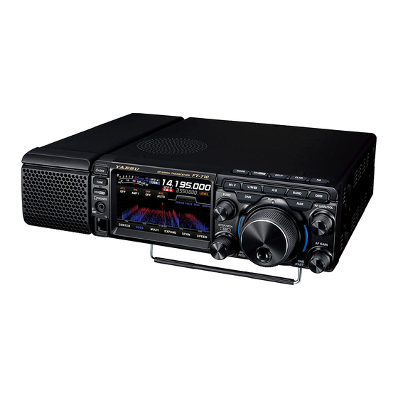
Yaesu FT-710 Operation Manual
Hf/50мhz transceiver
Hide thumbs
Also See for FT-710:
- Operation manual (116 pages) ,
- Manual (75 pages) ,
- Reference manual (26 pages)
Advertisement
Quick Links
Advertisement

Subscribe to Our Youtube Channel
Related Manuals for Yaesu FT-710


Summary of Contents for Yaesu FT-710
- Page 1 FT-710 Operation Manual...
- Page 3 About this Manual The FT-710 is a leading-edge transceiver with a number of new and exciting features, some of which may be unfamiliar to you. In order to gain the most enjoyment and operating efficiency from the FT-710, we recommend that you read this manual in its entirety, and keep it handy for reference as you explore the many capabilities of this new transceiver.
- Page 4 Table of Contents Safety Precautions .........4 Changing the number of ....... 28 Accessories & Options ........6 QMB channels ..........28 Supplied Accessories ......... 6 RX Clarifier ........... 30 Available options ..........6 TX Clarifier ............ 30 Installation and Interconnections ....7 Adjusting the Noise Blanker Level ....
- Page 5 Display the SD Card Information ....50 Optional Accessories ........51 FC-40 External Automatic Antenna Tuner (for Wire Antenna) ........... 51 Interconnections to FT-710 ......51 Setup the transceiver ........52 Tuning Operation ........... 52 FH-2 Remote Control Switches ......53 Resetting the Microprocessor .......54...
- Page 6 Safety Precautions Note beforehand that the company shall not be liable for any damages suffered by the customer or third parties in using this product, or for any failures and faults that occur during the use or misuse of this prod- uct, unless otherwise provided for under the law.
- Page 7 Do not allow metallic objects such as wires Refrain from using headphones and ear- and water to get inside the product. phones at a loud volume. This may result in fire, electric shock and equip- Continuous exposure to loud volumes may result ment failure.
- Page 8 Accessories & Options Supplied Accessories Hand Microphone SSM-75E DC Power Cord Spare Fuse (25A) 6.3 mm 3-contact Plug • Operation Manual • World Map • Sticker Available options • Hand Microphone (equivalent to the supplied microphone) SSM-75E • Reference Microphone •...
- Page 9 Construct the antenna and coaxial cable, or use a suitable antenna tuner, to maintain the impedance presented to the FT-710 antenna connector for an SWR of 1.5 or less. Careful preparation of the antenna and/or tuner will permit maximum performance, and protect the transceiver from damage.
- Page 10 Microphone, Headphone, Key, Keyer and FH-2 Connections φ3.5mm DOWN UP +5V MIC GND MIC PTT GND FAST (as viewed from front panel) Remote Control Keypad FH-2 (option) Key-up voltage is approximately +5.0 V DC, and key-down current is approximately 3 mA.
- Page 11 “CT-118” Connection Cable (option) Display connections The video digital output of the FT-710 transceiver can be shown on a large monitor. Use a commercially available DVI-D cable to connect a display monitor directly to the “EXT-DISPLAY” terminal (DVI-D) on the back of the FT-710.
- Page 12 By plugging the FH-2 Remote Control Keypad into When using an external monitor, set the setting this jack, direct access to the FT-710 CPU is pro- menu item “EXT DISPLAY” to “ON”. vided for control functions of the contest memory keying, and also frequency and function control.
- Page 13 SSM-75E Microphone Switches MUTE PTT Switch MUTE Key Switches Transmit/Receive. While pressing the MUTE key, the receiver audio Press to transmit and release to receive. from the speaker will be muted. DWN / UP Key Microphone The [UP]/[DWN] keys may also be used to manual- Speak into the microphone in a normal tone of ly scan the frequency upward or downward.
- Page 14 Display Indications It operates as an S meter in receive. In transmit, select the desired meter from: PO, COMP, ALC, VDD, ID, and SWR. Displays the current operation mode. In VFO mode, “VFO-A” or “VFO-B” is displayed. In memory mode, the type and chan- nel number of the recalled memory are displayed.
- Page 15 Meter Display Operation MODE Display S-Meter Displays the current operating mode. When touched the operation mode selection screen is displayed. Touch the desired operation mode to select it. RF power Output When the meter display screen is touched, the transmit meter selection screen is shown (the default setting is “PO”).
- Page 16 Frequency Display (VFO-A) Frequency Display (VFO-B) Exhibits the transmit and receive frequencies of Exhibits the transmit and receive frequencies of VFO-A. VFO-B. When the clarifier function is active, the offset fre- • Keyboard Frequency Entry quency is displayed. 1. Touch the “Hz” area of the frequency display. •...
- Page 17 Operation of the display [FUNC] knob Displays the multiple functions that may be operated when the [FUNC] knob is pressed. Normally, it is recommended to adjust the level of the spectrum scope with the [LEVEL] knob. The last used function is recalled when the [FUNC] knob is pressed. Therefor you can easily call up and then set a function by turning the [FUNC] knob.
- Page 18 Filter Function Display Displays the passband status of the DSP filter. The operation of WIDTH, SHIFT, NOTCH, CONTOUR etc. can be observed. Passband status of DSP filter (SHIFT, WIDTH) State of NOTCH State of CONTOUR Touch the filter display to reveal and check the setting value of the last used function from SHIFT, WIDTH, NOTCH, CONTOUR, and APF.
- Page 19 • Normally, select “AMP1”. lections until you are thoroughly familiar with the • The IPO can not only attenuate the input sig- performance of the FT-710. nal but also improve the intermodulation char- acteristics. It is most effective to operate the IPO first, and then use the ATT if the signal is still too strong.
- Page 20 The frequency span is shown on the horizontal X axis, the vertical Y axis depicts the signals and their strengths, and the time is represented on the receding Z axis. The FT-710 operator can intuitively grasp the band and signal conditions at any instant.
Need help?
Do you have a question about the FT-710 and is the answer not in the manual?
Questions and answers