Advertisement
Quick Links
Advertisement

Related Manuals for roomfitters FOMO-TVS-001-V1

Summary of Contents for roomfitters FOMO-TVS-001-V1
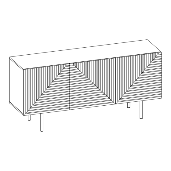
- Page 1 FOMO-TVS-001-V1 FOMO TV Stand/Sideboard...
- Page 2 THE PRODUCT MAY RECOMMENDED ASSEMBLING BY MORE THAN ONE PERSON. PLEASE ASK FOR ASSISTANCE AT YOUR CONVENIENCE BEFORE ASSEMBLING.
-
Page 3: Before You Start
Before You Start Read through each step carefully and follow the proper order Separate and count all your parts and hardware Give yourself enough room for the assembly process Have the following tools: Flat Head Screwdriver, #2 Phillips Head Screwdriver and Hammer Caution: If using a power drill or power screwdriver for screwing, please be aware to slow down and stop when screw is tight. - Page 5 BOTTOM LEFT RIGHT LEFT MIDDLE SHELF RIGHT MIDDLE SHELF SHELF x2 SHELF RIGHT AND LEFT END x2...
-
Page 6: Parts Identification
Parts Identification LOWER SUPPORT x2 BACK PANEL LEFT DOOR MIDDEL DOOR RIGHT DOOR Hardware Identification DOUBLE-HEADED SCREWDRIVER: THIS TOOL ALLOWS YOU TO USE DIFFERENT HEAD FOR DIFFERENT TYPE OF SCREWS BY SWITCH THE YELLOW HANDLE... - Page 7 DOOR TOUCH LATCH...
- Page 8 x 28...
- Page 9 Assemble screws Make sure screws are lockup evenly on board (hardware#4) vertically x 17 Proper orientation of CAM LOCK UNFINISHED SIDE...
- Page 10 Proper orientation of CAM LOCK...
- Page 11 Step 6 x 11 Step 7...
- Page 12 Step 8 Step 9...
- Page 13 Step 10 Proper orientation of CAM LOCK Step 11 Proper orientation of CAM LOCK...
- Page 14 Step 12 Step 13 √ × Make sure parts "L" and "A" a re assembled aligning with parts "H" and "T" x 24...
- Page 16 Follow the instructions printed on the plastic bag containing the tipping restraint hardware to attach thetip-over restraints to the unit and the wall. NOTE:The tipping restraint hardware included is for drywall construction. It will be necessary to drill holes for the wall anchors. Depending upon your wall construction, different anchor hardware mayberequired. Please contact your local hardware store for assistance.
- Page 18 YOU CAN MAKE GAP ADJUSTMENT WHEN DOORS DOES NOT OPEN CORRECTLY OR SMOOTHLY BY POP OUT THE EJECTOR PIN AND ROATE IT OUT TO THE PROPER LENGTH.
- Page 19 Safty Maximum Loads This unit has been designed to support the maximum loads shown. Exceeding these load limits could cause sagging,instability,product collapse,and/or serious injury. WARNING Please make sure that all objects are removed before moving the assembled unit. The unit must be team lifted, not dragged or pushed. Failure to do so could cause instability, product collapse, and/or serious injury.
Need help?
Do you have a question about the FOMO-TVS-001-V1 and is the answer not in the manual?
Questions and answers