
Related Manuals for WilTec American-Marsh Pumps SXT 10x10 490 Series


Summary of Contents for WilTec American-Marsh Pumps SXT 10x10 490 Series
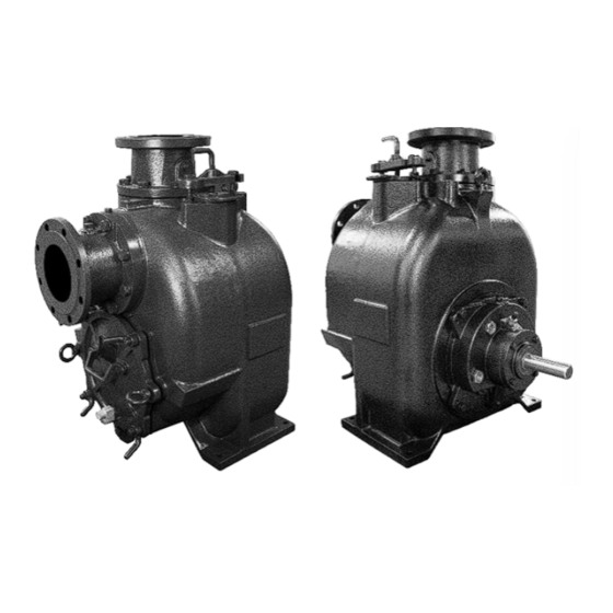
- Page 1 490 Series SXT 10”x10” Self-Priming Pumps Installation and Operating Manual *077-0244-000*...
-
Page 2: Table Of Contents
TABLE OF CONTENTS INTRODUCTION ........................- 3 - SAFETY SECTION A ........................- 5 - INSTALLATION SECTION B ......................- 6 - Pump Dimensions ......................- 6 - PREINSTALLATION INSPECTION ..................- 7 - POSITIONING PUMP ......................- 7 - Lifting ........................... - Page 3 Strainer Check ......................- 18 - Pump Vacuum Check ....................- 18 - STOPPING ......................... - 18 - Cold Weather Preservation ..................- 18 - BEARING TEMPERATURE CHECK ..................- 19 - TROUBLESHOOTING SECTION D ..................... - 19 - PREVENTIVE MAINTENANCE .................... - 21 - PUMP MAINTENANCE AND REPAIR SECTION E ..............
-
Page 4: Introduction
INTRODUCTION Thank You for purchasing an American-Marsh Pump. Read this manual carefully to learn how to safely install and operate your pump. Failure to do so could result in personal injury or damage to the pump. Because pump installations are seldom identical, this manual cannot possibly provide detailed instructions and precautions for every aspect of each specific application. - Page 5 HAZARD AND INSTRUCTION DEFINITIONS The following are used to alert maintenance personnel to procedures which require special attention, to those which could damage equipment, and to those which could be dangerous to personnel: DANGER: Immediate hazards which WILL result in severe personal injury or death. These instructions describe the procedure required and the injury which will result from failure to follow the procedure.
-
Page 6: Safety Section A
SAFETY SECTION A This information applies to the 490 Series SXT 10”x10” pumps. AMP has no control over or particular knowledge of the power source which will be used. Refer to the manual accompanying the power source before attempting to begin operation. This manual will alert personnel to known procedures which require special attention, to those which could damage equipment, and to those which could be dangerous to personnel. -
Page 7: Installation Section B
INSTALLATION SECTION B Review all SAFETY information in Section A. Since pump installations are seldom identical, this section offers only general recommendations and practices required to inspect, position, and arrange the pump and piping. Most of the information pertains to a standard static lift application where the pump is positioned above the free level of liquid to be pumped. -
Page 8: Preinstallation Inspection
PREINSTALLATION INSPECTION The pump assembly was inspected and tested before shipment from the factory. Before installation, inspect the pump for damage which may have occurred during shipment. Check as follows: Inspect the pump for cracks, dents, damaged threads, and other obvious damage. b. -
Page 9: Materials
losses. See the performance curve and operating range shown in SECTION E to be sure your overall application allows pump to operate within the safe operation range. Materials Either pipe or hose maybe used for suction and discharge lines; however, the materials must be compatible with the liquid being pumped. -
Page 10: Sealing
Sealing Since even a slight leak will affect priming, head, and capacity, especially when operating with a high suction lift, all connections in the suction line should be sealed with pipe dope to ensure an air-tight seal. Follow the sealant manufacturer's recommendations when selecting and applying the pipe dope. -
Page 11: Discharge Lines
Figure 2. Recommended Minimum Suction Line Submergence vs. Velocity DISCHARGE LINES Siphoning Do not terminate the discharge line at a level lower than that of the liquid being pumped unless a siphon breaker is used in the line. Otherwise, a siphoning action causing damage to the pump could result. -
Page 12: Bypass Lines
Bypass Lines Self‐priming pumps are not air compressors. During the priming cycle, air from the suction line must be vented to atmosphere on the discharge side. If the discharge line is open, this air will be vented through the discharge. However, if a check valve has been installed in the discharge line, the discharge side of the pump must be opened to atmospheric pressure through a bypass line installed between the pump discharge and the check valve. -
Page 13: Air Release Valve Installation
Figures 3 and 4 show a cross-sectional view of the Automatic Air Release Valve, and a corresponding description of operation. Figure 3. Valve in Open Position Figure 4. Valve in Closed Position During the priming cycle, air from the pump casing flows through the bypass line and passes through the Air Release Valve to the wet well (Figure 3). -
Page 14: Alignment
Figure 5. Typical Automatic Air Release Valve Installation Connect the valve outlet to a bleed line which slopes back to the wet well or sump. The bleed line must be the same size as the outlet opening or larger, depending on which Air Release Valve is being used. -
Page 15: Coupled Drives
When mounted at the AMP factory, driver and pump are aligned before shipment. Misalignment will occur in transit and handling. Pumps must be checked and realigned before operation. Before checking alignment, tighten the foundation bolts. The pump casing feet and/or pedestal feet, and the driver mounting bolts should also be tightly secured. -
Page 16: Drive Belts
Drive Belts When using drive belts, the power source and the pump must be parallel. Use a straightedge along the sides of the pulleys to ensure that the pulleys are properly aligned (see Figure 6C). In drive systems using two or more belts, make certain that the belts are a matched set; unmatched sets will cause accelerated belt wear. -
Page 17: Operation Section C
OPERATION SECTION C Review all SAFETY information in Section A. This pump is designed to handle liquids containing large, entrained solids and slurries. Do not attempt to pump volatile, corrosive, or flammable liquids which may damage the pump or endanger personnel as a result of pump failure. Pump speed and operating conditions must be within performance range shown in SECTION E. -
Page 18: Operation
If an electric motor is used to drive the pump, remove V‐belts, couplings, or otherwise disconnect the pump from the motor before checking motor rotation. Operate the motor independently while observing the direction of the motor shaft, or cooling fan. If rotation is incorrect on a three‐phase motor, have a qualified electrician interchange any two of the three phase wires to change direction. -
Page 19: Strainer Check
the pump by removing the casing drain plug. Use caution when removing the plug to prevent injury to personnel from hot liquid. As a safeguard against rupture or explosion due to heat, this pump is equipped with a pressure relief valve which will open if vapor pressure within the pump casing reaches a critical point. -
Page 20: Bearing Temperature Check
few hours, or if it has been pumping liquids containing a large amount of solids, drain the pump, and flush it thoroughly with clean water. To prevent large solids from clogging the drain port and preventing the pump from completely draining, insert a rod or stiff wire in the drain port, and agitate the liquid during the draining process. - Page 21 PUMP STOPS OR Air leak in suction line. Correct leak. FAILS TO DELIVER Lining of suction hose collapsed. Replace suction hose. RATED FLOW OR PRESSURE Leaking or worn seal or pump gasket. Check pump vacuum. Replace leaking or worn seal or gasket. Strainer clogged.
-
Page 22: Preventive Maintenance
PREVENTIVE MAINTENANCE Since pump applications are seldom identical, and pump wear is directly affected by such things as the abrasive qualities, pressure and temperature of the liquid being pumped, this section is intended only to provide general recommendations and practices for preventive maintenance. Regardless of the application however, following a routine preventive maintenance schedule will help assure trouble‐free performance and long life from your AMP pump. -
Page 23: Pump Maintenance And Repair Section E
PUMP MAINTENANCE AND REPAIR SECTION E MAINTENANCE AND REPAIR OF THE WEARING PARTS OF THE PUMP WILL MAINTAIN PEAK OPERATING PERFORMANCE. PERFORMANCE CURVE * STANDARD PERFORMANCE FOR PUMP MODEL SXT-10”X10” Based on 70°F (21° C) clear water at sea level with minimum suction lift. Since pump installations are seldom identical, your performance may be different due to such factors as viscosity, specific gravity, elevation, temperature, and impeller trim. -
Page 24: Illustration
ILLUSTRATION Figure E-1. Pump Model SXT-10”X10”... -
Page 25: Parts List
PARTS LIST Pump Model SXT-10”X10” Contact AMP to verify part numbers. Part Name Part Name Part Name Pipe Plug Press Relief Valve Seal Plate Gasket Suction Flange Cap screw Pipe Plug Check Valve Lock Washer Spring Washer Pivot Cap O-Ring Cap screw Lock Washer Wear Plate Assy... -
Page 26: Pump And Seal Disassembly And Reassembly
PUMP AND SEAL DISASSEMBLY AND REASSEMBLY Review all SAFETY information in Section A. Follow the instructions on all tags, label and decals attached to the pump. This pump requires little service due to its rugged, minimum‐maintenance design. However, if it becomes necessary to inspect or replace the wearing parts, follow these instructions which are keyed to the illustration (see Figure E-1) and the accompanying parts lists. -
Page 27: Suction Head And Wear Plate Removal
and reinstall the drain plug. For clean-out access, loosen the clamp screws (15) and clamp bars (13) securing the clean-out cover (12) to the suction head (10). To remove the check valve assembly, reach through the clean-out opening and remove the hardware (5 and 6) securing the check valve (3) to the suction flange (2) and suction head (10). - Page 28 from the shaft. NOTE Do not remove the impeller until the rotating assembly has been removed from the pump casing. Figure E-2. Loosening Impeller (Figure E-1) Inspect the impeller and replace it if cracked or badly worn. Slide the impeller adjusting shims (39) off the impeller shaft.
-
Page 29: Impeller Removal
for further disassembly. If no further disassembly is required, refer to Seal Installation. Figure E-3. Rotating Assembly Removal With Tool Impeller Removal (Figure E-1) Unscrew the impeller from the shaft in a counterclockwise direction (when facing the impeller). Use caution when unscrewing the impeller; tension on the shaft seal spring will be released as the impeller is removed. -
Page 30: Shaft And Bearing Removal And Disassembly
Shaft and Bearing Removal and Disassembly (Figure E-1) When the pump is properly operated and maintained, the bearing housing should not require dis- assembly. Disassemble the shaft and bearings only when there is evidence of wear or damage. Shaft and bearing disassembly in the field is not recommended. These operations should be performed only in a properly equipped shop by qualified personnel. - Page 31 Most cleaning solvents are toxic and flammable. Use them only in a well-ventilated area free from excessive heat, sparks, and flame. Read and follow all precautions printed on solvent containers. Inspect the shaft for distortion, nicks or scratches, or for thread damage on the impeller end. Dress small nicks and burrs with a fine file or emery cloth.
-
Page 32: Seal Installation
the oil seal from rolling as the shaft and bearings are installed in the bearing housing. The O.D. of the sleeve should be just smaller than the bearing housing bore, while the I.D. of the sleeve should be just larger than the O.D. of the lip seal area of the shaft. With the lip seal sleeve in place, lubricate the lip seal area of the shaft, and slide the shaft and assembled bearings into the bearing housing until the retaining ring on the outboard bearing seats against the bearing housing. - Page 33 Figure E-4. Cartridge Seal Assembly This seal is not designed for operation at temperatures above 160°F (71°C). Do not use at higher operating temperatures. If the wear plate (42) was removed, secure it to the seal plate (44) with the hardware (45 and 46). If the seal plate was removed, install the seal plate gasket (51) and bearing housing O-ring (49).
- Page 34 Clean and inspect the impeller as described in Impeller Installation and Adjustment. Install the full set of impeller shims (39) provided with the seal and screw the impeller onto the shaft until it is seated against the seal (see Figure E-5). A new seal assembly should be installed any time the old seal is removed from the pump.
-
Page 35: Impeller Installation And Adjustment
a non‐oil-based solvent and a clean, lint‐free tissue. Wipe lightly in a concentric pattern to avoid scratching the faces. Carefully wash all metallic parts in fresh cleaning solvent and allow to dry thoroughly. Do not attempt to separate the rotating portion of the seal from the shaft sleeve when reusing an old seal. -
Page 36: Rotating Assembly Installation
Rotating Assembly Installation (Figure E-1) Install the bearing housing and seal plate O-rings (43 and 50) and lubricate them with light grease. Ease the rotating assembly into the pump casing using the installation tool. Be careful not to damage the O-rings. Install the pump adapter ring (59) and secure it to the rotating assembly with the inner hardware (64 and 65). -
Page 37: Pressure Relief Valve Maintenance
NOTE If the suction flange (2) was removed, install the check valve and secure the body to the suction head with the shoulder type clamp (9). PRESSURE RELIEF VALVE MAINTENANCE (Figure E-1) The suction head is equipped with a pressure relief valve (26) to provide additional safety for the pump and operator (refer to Liquid Temperature And Overheating in OPERATION). -
Page 38: Power Source
Power Source Consult the literature supplied with the power source or contact your local power source representative. WARRANTY American-Marsh Pumps guarantees that only high-quality materials are used in the construction of our pumps and that machining and assembly are carried out to high standards. The pumps are guaranteed against defective materials and/or faulty craftsmanship for a period of one (1) year from the date of shipment unless specifically stated otherwise.
Need help?
Do you have a question about the American-Marsh Pumps SXT 10x10 490 Series and is the answer not in the manual?
Questions and answers