Table of Contents
Advertisement
Quick Links
M/DALI.1
KNX-DALI Gateway
Hardware Version: D
Datasheet
Issued: April 8, 2019
Edition V1.0.0
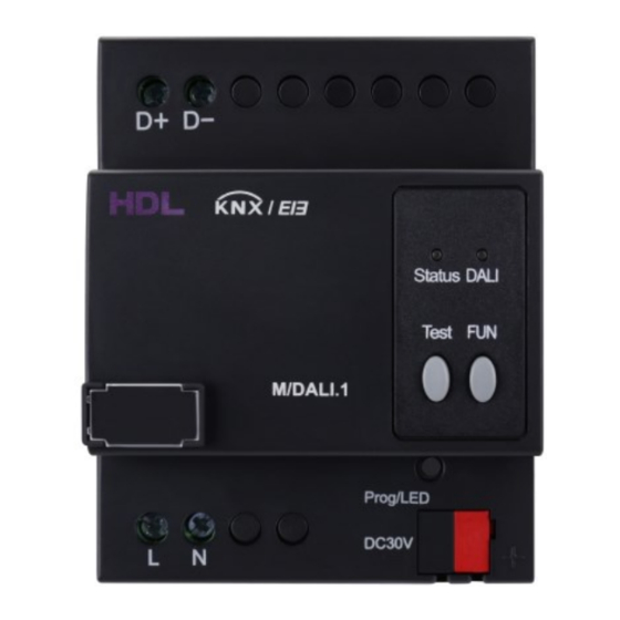
Figure 1. KNX-DALI Gateway
72mm
Figure 2. Dimensions - Front View
64mm
Figure 3. Dimensions - Side View
DALI ballast
...
DALI outputs
1
KNX
L N
Figure 4. Wiring
Overview
With built-in DALI power supply and a single DALI Bus,
DALI devices. Real-time failure detection enables the gateway to detect ballast failure and lamp failure etc.
Its main functions include:
Real-time failure detection for ballasts and lamps, etc.
■
Target control: Broadcast control, Channel control, Group control, Scene control, Staircase light control, Sequence
■
control, Emergency light control
Each channel and group supports Switch ON/OFF, Relative dimming, Absolute dimming, Status response function.
■
In conjunction with HDL KNX Assistant Software, DALI Gateway enables address management and assignment of
■
DALI ballast.
Group scene control supported, which can be configured and managed via HDL KNX Assistant Software.
■
Color temperature control function supported, which can be applied to broadcast, channel, group and scene control of
■
DT8 type color temperature control ballasts.
Online update.
■
Components and Operation
Dimensions - See Figure 2 and 3
Wiring - See Figure 4
1. Input voltage : 100~240V AC supported
2. DALI LED indicator:
- Keeps on in green when the module is working properly,
- Flashes in red when the DALI bus communicates
3. LED status indicator
4. TEST button
5. FUN button
6. KNX programming button/indicator: Red LED indicates programming mode.
7. KNX interface.
Functions of Button and LED indicator
- Red LED ON/OFF:
Short press the FUN button to broadcast control on or off, and the status indicator turns red. When broadcast on, red LED is
on; when broadcast off, red LED is off.
Keep pressing the FUN button for 30s to clear all the addresses. During the clearing process, the red status indicator will turn
on and off for three times, and the flashing interval is one second.
- Green LED ON:
Keep pressing the TEST button for 30s to reassign the address and the green status indicator flashes during the reassigning
process.
Short press the TEST button, and the ballasts will be on and off one second at a time. At this time, the green indicator indicates
the status of the ballasts.
In the case of a ballast that supports DT8 type color temperature control, the lamp will be lit up, and adjusted to the coolest color
temperature value, then adjusted to the warmest color temperature value, and finally extinguished, with each phase lasting for
1s.
Press the button "TEST" and "FUN" for 15 seconds simultaneously to restore the recorded fault ballast. During the recovery
process, the red status indicator and the green status indicator flash alternately, and the flashing interval is 1s. If there is no
ballast to restore, the red and green indicators keep on for 3s then turn off at the same time.
Installation
Installation - See Figure 5 - 7
Step 1. Fix the DIN rail with screws.
Step 2. Buckle the bottom cap of the KNX-DALI Gateway on the edge of the DIN rail.
Step 3. Press the device on the DIN rail, slide it and fix it up until an appropriate position is adjusted.
Note(s)
Installation - Distribution box
■
Programming - The device is compliant with the KNX standard and the parameters are set by the Engineering Tool
■
Software (ETS).
Total 64
KNX Bus voltage - 21~30V DC, no AC power supply allowed.
■
DALI ballast
Input voltage - 100~240V AC supported
■
Safety Precautions
The installation and commissioning of the device must be carried out by HDL or the organization designated by HDL.
■
For planning and construction of electric installations, the relevant guidelines, regulations and standards of the respec-
tive country are to be considered.
2
The device should be installed with DIN rail in DB box. HDL does not take responsibility for all the consequences
■
3
caused by installation and wire connection that are not in accordance with this document.
4
Please do not privately disassemble the device or change components, otherwise it may cause mechanical failure,
5
■
electric shock, fire or body injury.
6
Please resort to our customer service department or designated agencies for maintenance service. The warranty is not
■
applicable for the product fault caused by private disassembly.
7
Package Contents
M/DALI.1*1 / Label*5 / Datasheet*1
KNX-DALI Gateway (See Figure 1)
can be connectted to up to 64
.
1/2
Advertisement
Table of Contents

Subscribe to Our Youtube Channel
Related Manuals for HDL KNX-DALI


Summary of Contents for HDL KNX-DALI
- Page 1 For planning and construction of electric installations, the relevant guidelines, regulations and standards of the respec- tive country are to be considered. The device should be installed with DIN rail in DB box. HDL does not take responsibility for all the consequences ■...
- Page 2 The symbol “×” indicates that the content of the hazardous substance in at least one of the homogeneous materials of the part exceeds the limit requirement specified in the Standard IEC62321-2015. KNX Cable Guide KNX cable Black Technical support E-mail: support@hdlautomation.com Website: https://www.hdlautomation.com ©Copyright by HDL Automation Co., Ltd. All rights reserved. Specifications subject to change without notice.
Need help?
Do you have a question about the KNX-DALI and is the answer not in the manual?
Questions and answers