Table of Contents
Advertisement
Quick Links
Advertisement
Table of Contents
Troubleshooting

Related Manuals for LG LFXS24553S


Summary of Contents for LG LFXS24553S
- Page 1 REFRIGERATOR SERVICE MANUAL MODELS: LFXS24553S...
-
Page 2: Table Of Contents
CONTENTS SAFETY PRECAUTIONS ..............................1. SPECIFICATIONS ..............................2. PARTS IDENTIFICATION ............................3. DISASSEMBLY ................................REMOVING AND REPLACING REFRIGERATOR DOORS ..................DOOR ..................................DOOR ALIGNMENT ..................................FAN AND FAN MOTOR (EVAPORATOR) .................... -
Page 3: Specifications
1. SPECIFICATIONS MODELS LFXS24553S SPECIFICATIONS Color STAINLESS Dimensions (in) 32 3/4 X 35 3/8 X 69 3/4 (WXDXH) Net Weight (lb) 334 lb Capacity 24.4cu.ft. Refrigerant R134A Climate Class TEMPERATURE (N) Rated Rating 115/60 Cooling System FAN COOLING Temperature Control... -
Page 4: Parts Identification
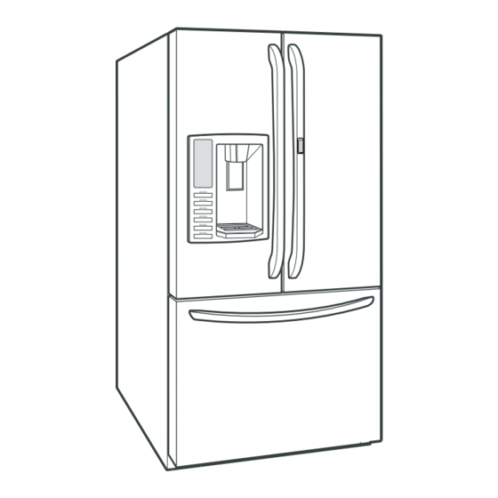
2. PARTS IDENTIFICATION ADJUSTABLE REFRIGERATOR SHELVING The refrigerator compartment shelves are adjustable to allow flexibility for storage needs. DOOR-IN-DOOR CASE REMOVABLE ICE STORAGE BIN The ice storage bin can be removed to fill ice buckets, coolers, or pitchers. LED INTERIOR LAMPS Refrigerator interior is lit by the LED array. -
Page 5: Disassembly
3. DISASSEMBLY 3-1 REMOVING AND REPLACING REFRIGERATOR DOORS Removing Refrigerator Door CAUTION: Before you begin, unplug the refrigerator. Remove food and bins from doors. Left Door -FIG. 2 1. Disconnect water supply tube by pushing back on the disconnect ring (3).-FIG. 1 2. -
Page 6: Door
3-2 DOOR Door Gasket Replacement 1. Insert gasket into channel Mullion Removal Press gasket into channels on the four remaining 1. Remove 2 screws. sides of door. Figure 5 Figure 1 2. Lift Mullion up carefully. Mullion Replacement 1. Connect wire harness. Figure 2 3. -
Page 7: Door Alignment
3-3 Door Alignment * Ice Fan Scroll Assembly Replacement If the level of refrigerator doors is uneven, follow the instructions below to align the doors: 1) Remove the plastic guide on the left side, using a Turn the leveling legs (CCW) to raise or (CW) to lower the phillips screwdriver to remove the screws. -
Page 8: Lamp
3-6 LAMP 4. Separate connector. Unplug, or disconnect power at the circuit breaker. If necessary, remove top shelf or shelves. 3-6-1 Refrigerator Compartment Lamp 1) Release 2 screws. 2) Hold both ends and pull down to remove. 5. Remove screw with driver. Figure 14 3) To remove the lamp case and cover, release 2 screws as shown. -
Page 9: Main Pcb
3-9 MAIN PCB 1) Loosen 3 screws on the PWB cover. Figure 26 Figure 27 5) Remove the 4) Holding the inner side of lead wire. the dispenser pull forward to remove. Figure 20 CAUTION: When replacing the dispenser cover make sure the lead wire does NOT come off and the water line 2) Remove the PCB cover is not pinched by the dispenser. - Page 10 3-13 WATER BUTTON ASSMEBLY 3-15 ICEMAKER REPLACEMENT 1) Remove screws. 1) Remove 4 screws as shown. 2) Grasp the Button assembly and lift. Button Lever Figure 31 Figure 33 2) Grasp the bottom of motor cover assembly and pull slowly. 3-14 ICE CORNER DOOR REPLACEMENT 1) Loosen the front screw as shown in the picture.
-
Page 11: Cap Duct Motor Replacement
CAUTION: Make sure that the motor housing is taped to 3-17 CAP DUCT MOTOR REPLACEMENT the mold, if not positioned correctly the cover will not fit 1) Separate the Housing of the Cap Duct Motor. properly. Figure 39 2) Unscrew 3 screws to disassemble the motor. Figure 36 Figure 40 3) When replacing the motor, check the position of the door... -
Page 12: How To Remove A Ice Bin
3-18 HOW TO REMOVE A ICE BIN 3-19 HOW TO INSERT A ICE BIN 1) Grip the handles, as shown. 1) Insert the Ice Bin, slightly tilting to avoid touching the Icemaker. (Especially, Ice-Detecting Sensor) Figure 44 Figure 47 2) Tilt and lift slightly as shown. Figure 45 3) Remove ice bin slowly. -
Page 13: How To Remove And Reinstall The Pullout Drawer
3-20 HOW TO REMOVE AND REINSTALL THE PULLOUT DRAWER 3-20-1 Follow Steps to Remove Step 1) Open the freezer door. Step 2) Remove the lower basket. Figure 48 Figure 49 Step 3) Remove 2 screws one on each side of the guide Step 4) Removal of the freezer door is done by lifting clear rails. - Page 14 3-20-2 Follow Steps to Reinstall Step 1) Reinstall the right side of the gear into the clip. Figure 53 Step 2) Insert the rail into the right side of the gear. Gears Step 3) Insert the rail into the left side of the gear, and do not need to be perpendicular to each other.
-
Page 15: Water Valve Disassembly Method
3-21 WATER VALVE DISASSEMBLY METHOD 3-22 FAN AND FAN MOTOR DISASSEMBLY METHOD 1) Turn off the water to unit. Remove the waterline from the 1) Remove screws for the Drain Pipe Assembly and the 1 valve. connected to the Motor Cover. MOTOR COVER Figure 64 Figure 60... - Page 16 3-23 Drawer Removal 3-24-2 DOOR BASKET OF HOME BAR DOOR Fully extend the drawer and lift from the front pulling straight out. The Door Baskets are removable for easy cleaning and adjustment. 1. To remove the Door Baskets, simply lifts the Door Baskets up and pulls straight out.
- Page 17 4. Separate the Home Bar. 3-24-4 HOW TO REMOVE AND REINSTALL THE HOMEBAR DOOR 1. Remove three Screws on the Top of Frame Door. 2. Pull Frame Door. up and out. 5. Pull THE DOOR FOAM ASSEMBLY, REFRIGERATOR up and out. 3-25 HOW TO REMOVE AND REINSTALL THE DOOR FOAM ASSEMBLY, REFRIGERATOR 1.
- Page 18 3-27 HOW TO REMOVE THE HOME BAR DOOR. 5. Separate the Cover. 1. Remove the screw located on the top of hinge. 2. Remove the cap hinge(upper) 3. Remove the bar by pushing it up from the bottom through the SVC hole (bottom hinge). 4.
-
Page 19: Adjustment
4. ADJUSTMENT 4-1 COMPRESSOR 4-2 INTRODUCTION OF E-LINEAR COMRESSOR 4-1-1 Role E-Linear compressor is run by mechanical part design The compressor intakes low temperature and low pressure through automatically varying the cooling power. The gas from the evaporator of the refrigerator and compresses main parts consist of compressor and Sub PCB which this gas to high-temperature and high-pressure gas. - Page 20 4-2-3 Compressor protection logic 4-2-4 Compressor problems diagnosis Since linear Comp conducts linear reciprocating motion, When there is a problem or failure with the `operation, we have protection logic for compressor, motor and PCB you are kindly recommended to check it as follows ; as the below.
- Page 21 2) Check to normality by measurement of Voltage 3) Check problems by LED On & Off Count _ (Sub PCB) Measure the resistance between pin of the connector (as If compressor protection logic is running, LED Lamp’s shown picture) with a multi-tester. blinking frequency of sub PCB, which takes in charge of control, can help estimate the protection logic’s symptoms and the cause of its problems.
-
Page 22: Circuit Diagram
5. CIRCUIT DIAGRAM... - Page 23 6. TROUBLESHOOTING 6-1 Error Code Summary WARNING: When checking Resistance values, make sure to turn off the power, and wait for the voltage to discharge. NOTE) Within 3 hours after the error : Press the Ice Plus button and Freezer button simultaneously 3 hours after the error : All errors, except for "E rt", "E SS", "E IS(except for Icing sensor)", "E gF", "E It"...
-
Page 24: Pcb Picture
7. PCB PICTURE 7-1 Main PCB P/ No & MFG Picture CON2 CON3 CON5 CON1 EBR792671** (2014.06~) CON6 CON201 CON7 CON4... - Page 25 7-2 Display PCB & Sub PCB P/No Picture Display PCB EBR786626xx (2014.06~) CON101 CON104 CON102 CON1 CON3 Sub PCB EBR60070711 (2014.06~) CON2...
-
Page 26: Troubleshooting With Error Display
8. Troubleshooting With Error Display 8-1 Freezer Sensor Error (E FS) Symptom Check Point 1. E FS 1. Check for a loose connection 2. Check Sensor Resistance CON7 Resistance [Ω] Short CON7 ICING-FAN Open pin ~ 16 GY/WH MOTOR BN/WH Other Normal C-FAN... - Page 27 Freezer Sensor Error (E FS) Reconnect or Is the Connector disconnected repair the Check the Sensor resistance. or loose between Main PCB and connector Is resistance normal? sensor? Check the Temperature and resistance refer to the table. No problem? CON7 CON7 Resistance [Ω] pin ~ 16...
- Page 28 8-2 Refrigerator Sensor Error (E rS) Symptom Check Point 1. E rS 1. Check for a loose connection 2. Check Sensor Resistance CON7 Resistance [Ω] Short CON7 Open pin ~ 14 Other Normal CON7 Resistance [Ω] pin ~ 14 23ºF / -5ºC 32ºF / 0ºC 41ºF / 5ºC 50ºF / 10ºC...
- Page 29 Refrigerator Sensor Error (E rS) Reconnect or Is the Connector disconnected repair the Check the Sensor resistance. or loose between Main PCB and connector Is resistance normal? sensor? Check the Temperature and resistance refer to the table. No problem? CON7 CON7 Resistance [Ω] pin ~ 14...
- Page 30 8-3 Icing Sensor Error (E IS) Symptom Check Point 1. E IS 1. Check for a loose connection 2. Check Sensor Resistance CON5 Resistance [Ω] CON5 Short pin ~ 17 Open Other Normal CON5 Resistance [ ] Ω pin ~ 17 -22ºF /-30ºC -13ºF /-25ºC -4ºF / -20ºC...
- Page 31 Icing Sensor Error (E IS) Reconnect or Is the Connector disconnected repair the Check the Sensor resistance. or loose between Main PCB and connector Is resistance normal? sensor? Check the Temperature and resistance refer to the table. No problem? CON5 CON5 Resistance [Ω] pin ~ 2...
- Page 32 8-4 Defrost Sensor Error (F dS) Symptom Check Point 1. F dS 1. Check for a loose connection 2. Check Sensor Resistance CON7 Resistance [Ω] Short CON7 Open pin ~ 18 Other Normal CON7 Resistance [Ω] pin ~ 18 23ºF / -5ºC 32ºF / 0ºC 41ºF / 5ºC 50ºF / 10ºC...
- Page 33 Defrost Sensor Error (F dS) Reconnect or Is the Connector disconnected repair the Check the Sensor resistance. or loose between Main PCB, connector Is resistance normal? Defrost controller and Sensor? Check the Temperature and resistance refer to the table. No problem? CON7 CON7 Resistance [Ω]...
- Page 34 8-5. Ice Maker Motor Error (E It) Symptom Check Point 1. E It 1. Check for a loose connection 2. Check Sensor Resistance CON4...
- Page 35 Ice Maker Motor Error (E It) Change the Explain to Main PCB Input Ice Maker test mode(Push customer Check the ice maker forward status The ice maker test button),check The voltage (1)~(2) point 0V? The Ice Tray,Ice maker motor Rotate? CON4 (2) ( 3) (1)Pin2, (2) Pin10, (3)Pin9...
- Page 36 8-5 Defrost Heater Error (F dH) Symptom Check Point 1. F dH 1. Check the door gasket 2. Check the Defrost control part 3. Check the PCB output voltage CON3 Resistance Part [Ω] FUSE-M Defrost Heater 34~42 22k ↑ Defrost Sensor TEST MODE 3 Voltage [V] CON3...
- Page 37 Defrost Heater Error (F dH) Input Test 3 Mode (Push the button 3 times) Replace the Replace Check the Door gasket . Door gasket Check the Heater Voltage. Main PCB Is door gasket damaged? Is voltage 220~240V? CON2 Change TEST MODE 3 Voltage [V] Fuse-M Check the Defrost control part.
- Page 38 8-6 Freezer Fan Error (E FF) Symptom Check Point 1. E FF 1. Check the air flow 2. Check the Fan Motor 2. Check the PCB Fan motor voltage Fan Motor CON7 TEST MODE 1 Voltage [V] CON7 8~12V pin ~ 12 CON7 Not 0V, 5V pin ~ 12...
- Page 39 Freezer Fan Error (E FF) Reset the unit and Input Test1 Mode. Replace (Push the button 1 time) Check the Fan Motor voltage Main PCB Is Fan Motor voltage 8~12V? CON7 TEST MODE 1 Voltage [V] Go to 3 Open the freezer door and Check CON7 the air flow.
- Page 40 8-7 Icing Fan Error (E IF) Symptom Check Point 1. E IF 1. Check the air flow 2. Check the Connector 2. Check the PCB Fan motor voltage Fan Motor CON7 TEST MODE 1 Voltage [V] CON7 8~12V pin ~ 5 CON7 Not 0V, 5V pin ~ 5...
- Page 41 Icing Fan Error(E IF) Reset the unit and Input Test1 Mode. Replace (Push the button 1 time) Check the Fan Motor voltage Main PCB Is Fan Motor voltage 8~12V? CON7 TEST MODE 1 Voltage [V] Go to 3 Open the freezer door and Check CON7 8~12V the air flow.
- Page 42 8-8 Condenser Fan Error (E CF) Symptom Check Point 1. E CF 1. Check the air flow 2. Check the Connector 2. Check the PCB Fan motor voltage Fan Motor CON7 TEST MODE 1 Voltage [V] CON7 8~12V pin ~ 6 CON7 Not 0V, 5V pin ~ 6...
- Page 43 Condenser Fan Error (E CF) Reset the unit and Input Test1 Mode. Replace (Push the button 1 time) Check the Fan Motor voltage Main PCB Is Fan Motor voltage 8~12V? CON7 TEST MODE 1 Voltage [V] Go to 3 Check the fan rotating. CON7 8~12V Does fan rotate?
- Page 44 8-9 Communication Error (E CO) Symptom Check Point 1. E CO 1. Check the loose connection 2. Check the Hinge connection CON5 CON101 CON101 CON104 CON102 Display CON101 Voltage [V] CON101 pin ~ 6 CON101 Not 0V, 5V pin ~ 5 CON101 Not 0V, 5V pin ~ 3...
- Page 45 Communication Error (Er CO) Change the Main PCB Check the voltage. Is CON101 5 pin ~ 3 voltage 0V or 5V? Check the loose connection Voltage Housing CON101 pin ~ 3 0V, 5V Check the Hinge (loose Check the voltage. connection) Is CON101 5 pin ~ 6...
- Page 46 9. Troubleshooting Without Error Display 9-1 Cube mode doesn’t work Symptom Check Point 1. Cube mode 1. Check the loose connection doesn’t work 2. Check the resistance CON2 CON1 CON3 Ice Maker Geared Motor Dispenser Motor...
- Page 47 9-1. Cube mode doesn’t work LEVER S/W Voltage [V] Resistance [Ω] Pushing 112~115V CON2 Geared Motor 31.1 ~ 42.1 pin ~ 4 0~2V Dispenser Motor 9.9 ~ 12.1 Pushing Pushing 9~12V CON3 5 pin ~ CON1 13 0~2V Pushing...
- Page 48 Cube mode doesn't work Replace Geared Motor Check the resistance value. Is Geared Motor resistance 144~ 176? ? Check the loose connection Geared Motor Change the Check the voltage. (while pushing the lever S/W) Is voltage correct? Resistance [Ω] Geared Motor 31.1 ~ 42.1 CON2 Replace...
- Page 49 9-2 Crush mode doesn’t work Symptom Check Point 1. Crush mode 1. Check the loose connection doesn’t work 2. Check the resistance CON2 CON1 CON3 Ice Maker Geared Motor Dispenser Motor...
- Page 50 9-2. Crush mode doesn’t work LEVER S/W Voltage [V] Resistance [Ω] Pushing 112~115V CON2 Geared Motor 31.1 ~ 42.1 pin ~ 12 0~2V Dispenser Motor 9.9 ~ 12.1 Pushing Pushing 9~12V CON3 5 pin ~ CON1 13 0~2V Pushing...
- Page 51 Crush mode doesn't work Replace Geared Motor Check the resistance value. Is Geared Motor resistance 87 ~ 107? ? Check the loose connection Geared Motor Change the Check the voltage. (while pushing the lever S/W) Is voltage correct? Resistance [Ω] Geared Motor 31.1 ~ 42.1 CON2...
- Page 52 9-3 Water mode doesn’t work Symptom Check Point 1. Water mode 1. Check the loose connection doesn’t work 2. Check the resistance valve CON2 LEVER S/W Voltage [V] Pushing 112~115V CON2 pin ~11 0~2V Pushing Resistance [Ω] Pilot Valve 360~420 Water valve 360~420...
- Page 53 Water mode doesn't work Replace Check the loose connection Water Valve Check the resistance value. Is Water Valve resistance 360~420 ? ? Change the Check the voltage. (while pushing the lever S/W) Is voltage correct? Water Valve Resistance [Ω] CON2 Water valve 360~420 LEVER S/W...
- Page 54 9-5 Refrigerator room lamp doesn’t work Symptom Check Point 1. Refrigerator room 1. Check the freezer door switch sticky lamp doesn’t work 2. Check the door S/W resistance 3. Check the LED Lamp Door S/W CON6 LED Lamp Resistance [ ] Ω...
- Page 55 Refrigerator room lamp doesn’t work Change the Change the Check the Freezer door switch. Door S/W Door S/W Check the LED Lamp voltage. Does it feel sticky? Is it 0~2V? (While door closed) Change the Check the door S/W resistance. Door S/W Is it correct compared with table? Change the...
- Page 56 9-5. Freezer room lamp doesn’t work Symptom Check Point 1. Freezer room lamp 1. Check the Refrigerator door switch sticky doesn’t work 2. Check the door S/W resistance 3. Check the LED Lamp F room LED Door S/W CON6 Hygiene Box Fan motor Resistance [Ω] Hygiene LED Normal...
- Page 57 Freezer room lamp doesn’t work Change the Change the Check the Refrigerator door switch. Door S/W LED Lamp Check the LED Lamp voltage Does it feel sticky? Is voltage 12V? (While door open) Change the Check the door S/W resistance. Door S/W Is it correct compared with table? Explain to customer...
- Page 58 9-6 Poor/over cooling in Fresh food section Symptom Check Point 1. Poor cooling in 1. Check the sensor resistance Fresh food section 2. Check the air flow 3. Check the air Temperature 4. Check the R -Damper motor voltage Duct Fan Motor CON7 CON7...
- Page 59 Poor cooling in Fresh food section Check the Compressor Check the air temperature. and sealed Is it cold? system Check the sensor resistance. Go to 7 CON7 Check the Fan Motor voltage CON7 Replace Is Fan Motor voltage 8~12V? Main PCB Resistance [Ω] pin ~ 14 23ºF / -5ºC...
- Page 60 9-7. Poor cooling in Freezer compartment Symptom Check Point 1. Poor cooling in 1. Check the sensor resistance Freezer compartment 2. Check the air flow 3. Check the air Temperature 4.Check the Fan motor sticky 4. Check the Fan motor voltage Duct Fan Motor CON7...
- Page 61 Poor cooling in Freezer compartment Check the Compressor Check the air temperature. and sealed Is it cold? system Check the sensor resistance. CON7 Change the CON7 Fan motor Check the Fan motor. Resistance [Ω] pin ~ 16 Rotate fan using hand. It feel sticky? -22ºF /-30ºC -13ºF /-25ºC...
- Page 62 Replace Main PCB Check the Fan Motor voltage Is Fan Motor voltage 8~12V? CON7 TEST MODE 1 Voltage [V] CON7 8~12V pin ~ 12 Change the Check the Fan Motor voltage motor Is Fan Feed Back voltage 1~5V? CON7 TEST MODE 1 Voltage [V] CON7 Not 0V, 5V...
- Page 63 9-9. Hygiene fan doesn’t work Symptom Check Point 1. Hygiene fan 1. Check Hygiene Fan motor voltage doesn’t work 2. Main PCB Hygiene Fan motor CON6 Voltage [V] CON6 pin ~ 13...
- Page 64 Hygiene fan doesn’t work Change the Change the Fan motor Check the Hygiene voltage Choose the Hygiene Max in display Is voltage 12V? (While door open) Check the PCB Voltage. Is CON6 2nd pin ~ 13th pin voltage 12V? CON6 Voltage [V] CON6 pin ~13...
- Page 65 9-10. Hygiene LED doesn’t work Symptom Check Point 1. Hygiene LED 1. Check Hygiene LED voltage doesn’t work 2. Main PCB Hygiene Fan motor CON6 Voltage [V] CON6 pin ~ 6...
- Page 66 Hygiene LED doesn’t work Change the Change the Fan motor Check the Hygiene LED voltage Choose the Hygiene Max in display Is voltage 12V? (While door open) Check the PCB Voltage. Is CON6 4 pin ~ 6 voltage 12V? CON6 Voltage [V] CON6 pin ~ 6...
-
Page 67: Reference
10. Reference 10-1 TEST MODE and Removing TPA 1. How to enter the TEST MODE Push the test button on the Main PCB to enter the TEST MODE. * 1 time : Comp / Damper / All FAN on (Everything is displayed) * 2 times : Damper closed (22 22 displayed) * 3 times : Forced defrost mode... - Page 68 10-2 TEMPERATRUE CHART - FRZ AND ICING SENSOR TEMP RESISTANCE VOLTAGE -39°F (-40°C) 4.09 V 73.29 kΩ -30°F (-35°C) 3.84 V 53.63 kΩ -21°F (-30°C) 3.55 V 39.66 kΩ -13°F (-25°C) 3.23 V 29.62 kΩ -4°F (-20°C) 2.89 V 22.33 kΩ 5°F (-15°C) 16.99 kΩ...
- Page 69 10-3 TEMPERATRUE CHART - REF AND DEF SENSOR TEMP RESISTANCE VOLTAGE -39°F (-40°C) 4.48 V 225.1 kΩ -30°F (-35°C) 4.33 V 169.8 kΩ -21°F (-30°C) 4.16 V 129.3 kΩ -13°F (-25°C) 3.95 V 99.30 kΩ -4°F (-20°C) 3.734 V 76.96 kΩ 5°F (-15°C) 60.13 kΩ...
- Page 70 Compressor Troubleshooting Step 1) Open PWB cover Step 2) Check for blinking frequency of LED, PWB If compressor is normal, it does not blink : Refer to the next page to find out what actions to take according to how many times LED blink...
- Page 71 Actions to take according to Led blinking frequency LED operating condition Cause Service guideline 1.After resetting LED two - time repetiton power, check if it is PCB part running normal defect 2.If the same (piston symptom arises after overrun) - off - - off - - off repeating...
- Page 72 10-4 How to check the Fan-Error (1) EBR650027** After sending a signal to the fan, the MICOM checks the BLDC fan motor s lock status. If there is no feedback signal from the BLDC fan, the fan motor stops for 10 seconds and then is powered again for 15 seconds.
-
Page 73: Component Testing Information
11. COMPONENT TESTING INFORMATION 11-1 Defrost Controller Assembly Function The controller assembly is made up of two different kinds of parts. The fuse and the sensor. To determine if these parts are defective, check for resistance. The fuse will cut power to the defrost heater at very high temperatures. - Page 74 11-2 Sheath Heater Function Sheath heater is a part for defrost. All heating wire is connected to only one line. To check if the part is defective, check the resistance. How to Measure (1) (2) Set a ohmmeter connect to The 2 housing pin. Measure the 2 pin connected to Sheath Heater.
- Page 75 11-3 Door Heater Assembly Function The heater is designed to prevent the door from sweating. How to Measure Check the Brown to Blue at CON2 on the sub PCB Sub PCB Standard Test Point Result (1) to (2) 2.3 ~ 2.9...
- Page 76 11-4 DOOR SWITCH, Freezer Function The switch senses if the door is open or closed. - When the door open, lamp on. - When the door open, the switch give information to Micom. When the door open, internal contact operate on and off moving plunger of door switch up and down.
- Page 77 11-5 DOOR SWITCH, Refrigerator Function The switch senses if the door is open or closed. - When the door open, lamp on. - When the door open, the switch give information to Micom. When the door open, internal contact operate on and off moving plunger of door switch up and down.
- Page 78 11-6 Dispenser DC Motor Function - Dispenser DC Motor : When customer push the dispenser button, Pull duct door and abstract from ice bank. How to Measure Dispensor DC Motor Standard Dispenser DC Motor Test Points Result (1) to (2) 9.9 ~ 12.1...
- Page 79 11-7 AC Motor ASSEMBLY Function The motor in the door pushed the ice into the dispenser. How to < In-door Motor > < In-door Motor > Measure Separate the Separate the housing. housing. Measure the Measure the resistance between resistance between (1) and (2) (1) and (3) Check the resistance between connectors (In-door motor 1, 2) and...
- Page 80 11-8 Damper Function The damper supplies cold air from the freezer to the chill room using the damper plate. The chill room is colder when the damper plate is open. When the damper is closed the chill rooms temperature will rise. How to Measure <...
- Page 81 11-9 Flow Sensor Function Flow Sensor (in machine room) Count the water quantity from city water to water filter in refrigerator How to Measure Flow Sensor (in machine room) Standard Test Points Result Red wire to Black wire 4 ~ 30...
- Page 82 12. TROUBLESHOOTING 12-1 INFORMATION OF LINEAR COMPRESSOR The information tag provides compressor model, refrigerant, serial number and safety approval Compressor Label 1. Compressor Model F L B 0 7 5 L A N A Operating Type Series name A : A-Inverter DLF/FA/FB E : E-Inverter Displacement...
- Page 83 To reduce noise level, the piston stroke is slowly increased to full power during start up. Step 1) Start up - Half stroke interval for first 30 seconds. Step 2) Ramp up - Stroke increases every 0.8sec until maximum stroke length is reached (about 3 min, 15 sec) Step 3) CVCF interval - 180V / 60Hz Step 1) Start up - Half stroke interval for first 20...
- Page 84 CON201 Time>30sec Power off Power ON PCB OK Disconnect ≒ Y& V 200 Replace drver Comp FLB075(A-Inverter) Ref. Display & sound Refer TEST1 Forced Starting TDC (Full Stroke) Display ON, Buzz 1 time...
- Page 85 12-1 Check A Dear is PC board located in the PCB case. The control driver is PC board for the compressor. This step shows the source voltage of the driver PC board. Step 1. Open PCB Cover Step 2. Check Driver PCB * Driver PCB located in machine room.
- Page 86 12-1 Check B B1. LED blinks once, then repeats (FCT0 Fault: A-Inverter) Blink OFF Blink OFF - Purpose: Detecting motor current and voltage error - Check voltage at point A (Motor Voltage), point B (Motor Current) and Point C (Capacitor Voltage) when compressor is off.
- Page 88 Protection Compressor blink 6 times logic Intermittently (Current Trip)check B5 Check B Works Replace IPM Check Driver PCB Compressor Replace Damage Compressor Check Reset Repeat Current trip Power Check Procedure occur? Replace Compressor Cycle blockage? Compressor Doesn’t works Sealed system Cycle check Repair...
- Page 92 12-2 SERVICE DIAGNOSIS CHART COMPLAINT POINTS TO BE CHECKED REMEDY • Is the power cord unplugged from the outlet? • Plug into the outlet. No Cooling. • Check if the power switch is set to OFF. • Set the switch to ON. •...
- Page 93 12-3 REFRIGERATION CYCLE Troubleshooting Chart TEMPERATURE STATE OF STATE OF THE OF THE CAUSE REMARKS THE UNIT EVAPORATOR COMPRESSOR PARTIAL Freezer Low flowing sound of A little higher than • Refrigerant level is low due LEAKAGE compartment and Refrigerant is heard ambient to a leak.
- Page 94 12-3-2 SEALED SYSTEM DIAGNOSIS “Not Cooling” Complaint All components operating, No airflow problems, Not frosted up as a defrost problem problem has been isolated to sealed system area Frost Partial None Pattern? Equalization Equalization Test Test Very Fast Very Slow Very Slow Very Fast Fast...
-
Page 95: Icemaker Operating Method And Troubleshooting
13. ICEMAKER OPERATING METHOD AND TROUBLE SHOOTING 13-1 Icemaker’s Basic Operating Method Power On Power On Start Position • Adjusts Ice Tray to Start Position with power on. • Adjusts Ice Tray to Start Position with power on. • Waits until water becomes ice. Icemaking For cold air circulation, Ice tray will be Mode... - Page 96 13-2 ICE MAKER FUNCTIONS 13-2-1 Icemaking Mode 1. Icemaking Mode begins right after the ice tray fills with water. 2. Icemaker waits until water becomes ice in the ice tray. Ice-detecting sensor checks if the ice bin is full every 2min. 13-2-2 Harvest Mode At least in 110min, since icemaker begun icemaking mode, Icemaker starts to twist the ice tray to drop ices into the Ice bin.
- Page 97 13-3-2 Icemaker not making ice or not making enough ice (Icemaker Unit & Ice-detecting sensor Diagnosis) Icemaker Unit and Ice-detecting sensor Diagnosis The icemaker unit and Ice-detecting sensor is programmed to be diagnosed. Follow the procedure step by step to check to see if icemaker and Ice-detecting sensor is working normally. Icemaker Unit Ice-detecting sensor Fill Key...
- Page 98 STEP (Ice-detecting sensor Diagnosis) 2. Close the left door 1. Remove Ice bin from compartment 3. Wait for 3min. 4. Freezer door stays open 5. Push the refrigerator button & lock button at the same time. is shown on the display after the procedure above, Ice-detecting sensor is normal. FULL is shown on the display after the procedure above, Ice-detecting sensor is abnormal.
-
Page 99: Description Of Function & Circuit Of Micom
14. DESCRIPTION OF FUNCTION & CIRCUIT OF MICOM 14-1 FUNCTION 14-1-1 Function 1. When the appliance is plugged in, it is set to 37°F for Refrigerator and 0°F for freezer. You can adjust the Refrigerator and the Freezer control temperature by pressing the ADJUST button. 2. - Page 100 14-1-4 Filter condition display function 1. There is a replacement indicator light for the filter cartridge on the dispenser. 2. Water filter needs replacement once six months or of using water filter. 3. When the Water Filter Icon blinks, you must exchange the filter.
- Page 101 14-1-7 CONTROL OF FREEZER FAN MOTOR 1. Freezer fan motor has high and standard speeds. 2. High speed is used at power-up, for Ultra Ice, and when refrigerator is overloaded. Standard speeds is used for general purposes. 3. To improve cooling speed, the RPM of the freezer fan motor change from normal speed to high. 4.
- Page 102 14-1-13 Defrosting (removing frost) 1. Defrosting starts each time the COMPRESSOR running time Betwee 7~50 hours. 2. For initial power on or for restoring power, defrosting starts when the compressor running time reaches 4 hours. 3. Defrosting stops if the sensor temperature reaches 46.4°F(8°C) or more. If the sensor doesn’t reach 46.4°F(8°C) in 1 hours, the defrost mode is malfunctioning.
-
Page 103: Exploded View
#EV# 15. EXPLODED VIEW CASE PARTS 503F 611E 409D 611F 281A 409A 607A 158A 271B 103B 103A 282E 120A 104E 501F 282F 120B 319F 329B 405J 405C 410G 145A 405F 271A 501A 145B 405A 411A 404B 319G 304A 158C 282D 409B 282B 406B... - Page 104 #EV# REFRIGERATOR PARTS 140D 140D 141A 141A 140E 140E 141B 141B 141E 141D 140D 149C 141A 149E 140E 141B 167B 154A 151C 145G 145J 151A 151B 154B 145H 128B 170A 128A...
- Page 105 #EV# FREEZER PARTS 133B 136B 145C 131A 136C 133A 145F 132P 136D 136A...
- Page 106 #EV# DOOR PARTS 241D 230B 250W 230C 231B 233B 230A 271C 233C 232A 230D 231C 233J 241D 232D 233D 231D 212J 212G 241G 212K 212J 241K 241J 232B 212K 232C 631A 244B 241H 212K 212J 212J 241L 243C 615A 619B 244A 611A 262E...
- Page 107 #EV# VALVE & WATER TUBE PARTS 625A 623B 616J 623B 616J 627D 627A 619A 627B...
- Page 108 #EV# ICEMAKER & BIN PARTS 630J 600A 630J 600C 630F 600B 630A 630H 606A 630G...
- Page 109 P/No. MFL62526051 Aug, 2014...
Need help?
Do you have a question about the LFXS24553S and is the answer not in the manual?
Questions and answers