
Subscribe to Our Youtube Channel
Related Manuals for SMC Corporation LECP6 Series


Summary of Contents for SMC Corporation LECP6 Series
- Page 1 Doc. no. LEC-OM00607 PRODUCT NAME Step Motor Controller (Servo / 24VDC) MODEL / Series / Product Number LECP6 Series...
-
Page 2: Table Of Contents
Contents 1. Safety Instructions..................4 2. Product Outline ....................6 2.1 Product features ..................6 2.2 How to Order....................7 2.3 Product configuration ................8 2.4 Start up Procedures ..................9 (1) Confirmation of the package content ...........9 (2) Installation....................9 (3) Wiring and connection ................9 (4) Power ON alarm (error) ................10 (5) Operation pattern setting ..............10 (6) Trial run (actuator adjustment)............10 3. - Page 3 (2) Wiring of the stop switch ..............19 (3) Wiring of the lock release ..............19 5.4 Stop circuits .....................20 (1) Example circuit 1- Single controller with teaching Box ....20 (2) Example circuit 2 - multiple controllers (Stop relay contact (1)) ..21 (3) Example circuit 3 - Motor power shutdown (relay contact (2)) ..22 6.
- Page 4 [7] Area output....................43 11. Option......................44 11.1 Actuator cable (5m or less) ..............0 11.2 Actuator cable (8-20m) ................44 11.3 Actuator cable for with lock (5m or less) ..........0 11.4 Actuator cable for with lock (8-20m) ............0 11.5 I/O Cable ....................0 11.6 Controller setting kit................46 11.7 Teaching box..................47 12.
-
Page 5: Safety Instructions
LECP6 Series / Controller 1. Safety Instructions These safety instructions are intended to prevent hazardous situations and/or equipment damage. These instructions indicate the level of potential hazard with the labels of “Caution,” “Warning” or “Danger.” They are all important notes for safety and must be followed in addition to International Standards (ISO/IEC), Japan Industrial Standards (JIS)*1) and other safety regulations*2). - Page 6 LECP6 Series / Controller 1. Safety Instructions Caution The product is provided for use in manufacturing industries. The product herein described is basically provided for peaceful use in manufacturing industries. If considering using the product in other industries, consult SMC beforehand and exchange specifications or a contract if necessary.
-
Page 7: Product Outline
2. Product Outline 2.1 Product features The followings are the main functions of this controller: Actuator control A positioning operation and operation at a specific speed and force for the actuator are possible by controlling the servo motor. Specified force operation Control the pushing force or the pressing force of the actuator. -
Page 8: How To Order
2.2 How to Order The part number construction for this product is as follows: L E C P 6 N Controller Actuator part number Compatible motor (“LE” to “Stroke” of the actuator part number) Step motor (Servo / 24VDC) Example: If “LEHZ10LK2-4AF-R16N1D” is the Number of step data complete actuator part number, “LEHZ10LK2-4”... -
Page 9: Product Configuration
2.3 Product configuration The product configuration of this controller is as follows. (*1) ●I/O cable (*1) Part No: LEC-CN5- □ ● Electric Actuator ●Controller (*3) Power supply 24VDC To CN5 Option ● Communication To CN4 (*1) cable To CN4 ●Actuator cable To CN3 Part No: (*2) -
Page 10: Start Up Procedures
2.4 Start up Procedures Before using this controller, please connect cables and startup using the following procedures. (1) Confirmation of the package content When you open the product package for the first time; please check the package contents to confirm the controller, label indication, quantity of accessories, etc. -
Page 11: Power On Alarm (Error)
(4) Power ON alarm (error) Ensure the stop is not activated and then supply 24VDC power. LED color Status Function Green Normal POWER Error ALARM Controller If the LED [PWR] lights in green, the controller is in the normal condition. However, if the LED [ALM] lights in red, the controller is in the alarm (error) condition. -
Page 12: Product Specifications
3. Product Specifications 3.1 Basic specifications The basic specifications of this controller are as follows: Item Specifications Compatible motor Step Motor (Servo / 24VDC) Power voltage:24VDC +/-10% (*2) Max.current consumption: 3A(Peak 5A) (*1) (*3) Power supply (for both of motor drive power,control power, stop,lock brake release) Parallel input 11 inputs (photo-coupler isolation) -
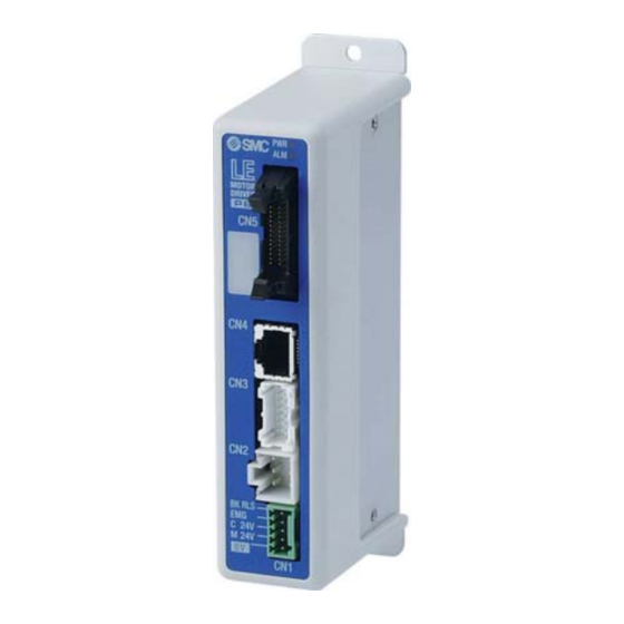
Page 13: Parts Description
3.2 Parts description The detailed descriptions of each part are as follows: Side (controller version) SV1.00 ARX8300073 Label of controller version (Example) controller version “SV1.00” (10) Side Label Name Description Power ON/No alarm: Green light Data (step data, parameter) writing /green light flashing caution Power LED (green) Do not turn off the controller input power or remove the... -
Page 14: Outside Dimension Diagram
3.3 Outside dimension diagram The outside view of this product is as shown in the diagram below: (1) Screw mount type (LECP6□□-□) (2) DIN rail mount type (LECP6□□D-□) - 13 -... -
Page 15: How To Install
3.4 How to install (1) How to install There are two types of controllers; screw mount type and DIN rail mount type. The followings are the descriptions on how to install each type: [1] Screw mount type (LECP6□□-□) [2] DIN rail mount type (LECP6□□D-□) (Installation with two M4 screws) (Installation with the DIN rail) DIN rail is locked. -
Page 16: Installation Location
Caution (1) The earthling should be the dedicated grounding point. It should be a functional ground with less than 100 Ω resistance. (2) The cross section of the grounding wire should be greater than 2mm The ground point should be near this controller to make the wire length shorter. Controller Controller Other device... -
Page 17: External Wiring Diagram
4. External Wiring Diagram The typical connections for each connector of this controller (CN1 to CN5) are as shown below. 4.1 CN1: Power connector Controller Controller power supply 24VDC Power cable (The 24VDC power supply and the power cable should be obtained separately.) * Please refer to “5. -
Page 18: Connection With A Pc
(2) Connection with a PC * Controller setting kit ( Controller setting software, communication cable, USB cable and the conversion unit are provided.) Conversion Controller unit USB cable モニタ モニタ 120.3 120.3 動作中 動作中 現在位置 現在位置 現在速度 現在速度 mm/s mm/s アラーム... -
Page 19: Cn1: Power Supply Plug
5. CN1: Power supply plug 5.1 Power supply plug specifications The specifications of the provided power supply plug are as follows. Power supply plug Terminal Function Descriptions The negative common power for M24V, Common power (-) C24V, EMG and BK RLS. The positive power for the actuator motor to M24V Motor power (+) -
Page 20: Wiring Of Power Supply Plug
5.3 Wiring of power supply plug Connect the power supply plug to the 24VDC controller power supply according to instructions (1) (2) and (3) and then, insert it into the CN1 connector of the controller. (1) Wiring of the power supply Connect the positive of the 24VDC controller power supply to the C24V and M24V. -
Page 21: Stop Circuits
5.4 Stop circuits The controller can provide a ‘controlled stop’when the +24 VDC is removed from the ‘EMG’ pin. In a controlled stop condition the controller decelerates the actuator with maximum deceleration value for the actuator The stop switch on the teaching box causes a controlled stop if activated. ... -
Page 22: Example Circuit 2 - Multiple Controllers (Stop Relay Contact (1))
(2) Example circuit 2 - multiple controllers (Stop relay contact (1)) If the system where this controller is installed has a stop circuit for whole system, or if the system has multiple controllers with individual power supply, relay contacts should be made between the 24VDC controller power supply and the EMG terminal of the power supply plug. -
Page 23: Example Circuit 3 - Motor Power Shutdown (Relay Contact (2))
(3) Example circuit 3 - Motor power shutdown (relay contact (2)) If there is a necessity to have circuit to shutdown the motor power externally, relay contacts should be made between the 24VDC controller power supply and the M24V and EMG terminal of the power supply plug. -
Page 24: Cn5: Parallel L/O Connector
6. CN5: Parallel l/O Connector 6.1 Parallel I/O specifications * Input specifications * Output specifications Item Specification Item Specification Internal circuit and photo Internal circuit and photo Input circuit Output circuit coupler isolation coupler Isolation Number of Number of outputs 13 outputs 11 inputs inputs... -
Page 25: The Parallel I/O Signal Is Detailed
6.3 The parallel I/O signal is detailed I/O cable Connector for CN5 of the controller The end to be connected to a PLC, etc. - Input terminal- Function Description COM+ The terminal for the 24V of the 24VDC I/O signal power. COM- The terminal for the 0V of the 24VDC I/O signal power. - Page 26 Effective condition of the Parallel I/O signal Condition SETON SVRE BUSY Signal name SETUP OFF(*1) (Return to origin) DRIVE (Operation start instruction) (“-“ = It doesn't depend In the ON/OFF state of the each output signal) *1 During the positioning operation the SETUP input will be disabled whilst hold is in operation. Caution SETUP and DRIVE can only be accepted during the above conditions.
- Page 27 Caution (1)After pushing operation is finished, even if controller changes to energy saving mode,”INP” signal status maintains to ON. INP(ON) force (Example) Step data“force”is 100% continue Step data“Trigger LV”is 80%, time The energy saving setting of the actuator is 40%(*1) (2) If controller version is below SV1.00 .
-
Page 28: Parallel I/O Wiring Example
6.4 Parallel I/O Wiring Example When you connect a PLC, etc. to the CN5 parallel I/O connector, please use the I/O cable (LEC-CN5-□). The wiring should be changed depending on the type of the parallel I/O (NPN or PNP). Please wire referring to the following diagram * NPN type * PNP type I/O signal power... -
Page 29: Setting Data Entry
7. Setting Data Entry In order to move the actuator to a specific position, it is necessary to setup the patterns of operations with a PC (with the controller setting software) or the teaching box. This setup data input by the software or teaching box will be recorded in the memory of the controller. - Page 30 Details of step data Setting name Range Description Number of the step data. 0 to 63 The setting to specify the coordinate system for the target position. Software Description Blank Disable The step data is ineffective. 3 options The target position will be defined by MovementMOD (See the right Absolute...
- Page 31 * Effective only for the pushing operation (when the value for the “Pushing force” is from 1to 100). This defines the movement speed during the pushing operation. If this Minimum value to Speed is too high, it may cause damage to the actuator or work piece due to Pushing speed “Max force”...
-
Page 32: Basic Parameter
7.2 Basic parameter The “Basic parameter” is the data to define the operating conditions of the controller, conditions of the actuator, etc. Details of basic parameter Activation: “XX” = Become effective just after recorded into the controller “X” = Become effective after restarting the controller “-“... - Page 33 This defines the position of the actuator after the return to origin operation. (Unit: mm) * The ORIG offset is 0 (mm). Actuator Between the left examples, the actuator positions are not The position recognized by the different but the reference point controller after the return to the origin operation (0mm).
-
Page 34: Return To Origin Parameter
7.3 Return to origin parameter The “Return to origin parameter” is the setting data for the return to origin operation. Details of Return to origin parameter Activation: “XX” = Become effective just after recorded into the controller, “X” = Become effective after restarting the controller, “-“... -
Page 35: Return To Origin
8. Return to origin 8.1 Return to origin After entering the setting data, it is necessary to perform a return to origin operation before starting the positioning or pushing operation. (To ensure the position of origin) * The return to origin direction is dependent on the actuator. ... -
Page 36: Pushing Operation
8.3 Pushing operation The pushing operation is active when a Value greater than “1” is set in the Step data"pushing force". Similar to the positioning operation, the actuator moves according to the settings of “Position” and “Speed” in the step data and then, when it reaches to the target position, it starts the pushing process. The actuator pushes the load with the force no more than the maximum force set in the “Pushing force”... -
Page 37: Controller Input Signal Response Time
Pushing process Speed Position Target position Positioning range (In position) (2) Movement of the workpiece in the direction opposite to the pushing direction (The actuator is pushed back since the reaction force from the workpiece is too large.) After completion of the pushing operation, if the reaction force from the workpiece becomes larger, the actuator may be pushed back. -
Page 38: Operation (Example)
9. Operation (example) 9.1 Positioning operation Example) Move an actuator from the origin to 50mm point with 100mm/s. (Using Step No.1) Next, it shows setting example to move the actuator from the 50mm point to 100mm point by moving it 5 times continuously, 10mm at a time, with a speed of 50 mm/s.(Step No. -
Page 39: Pushing Operation
9.2 Pushing operation Example) Move an actuator from the origin to 100mm point with 100mm/s. (Using Step No.1) From the 100mm point, the actuator starts the pushing operation of 10mm/s speed and 50% or less force (the pushing distance is up to 5mm). Then, the actuator moves from the position where the pushing operation was completed (where INP was turned on) to the 50mm point with 50mm/s. -
Page 40: Operation Instruction
10. Operation instruction 10.1 Outline of the operation instruction The operation of the actuator can be achieved by specifying the number of step data recorded in the controller via the I/O signal. An effective state of the parallel I/O signal is shown in the following. 10.2 Procedures with the Parallel I/O Please refer to the following “Procedures”... -
Page 41: Positioning Operation
[2] Positioning operation -Timing chart- - Procedures- (1) Input step data No. (IN0 to IN5) Input the step Scan the step data no. data no. ↓ (2) DRIVE is turned ON. Power →Scan the step data number (from IN0 to IN5). IN0~5 * Then, if DRIVE is turned OFF, the step data ・... -
Page 42: Pushing Operation
[3] Pushing operation - Procedures- - Timing chart - (1) Input step data No. (IN0 to IN5) Input the step Scan the step ↓ data no. data no. (2) DRIVE is turned ON. (OUT0-5 is turned off.) Power →Scan the step data number (from IN0 to IN0~5 IN5). -
Page 43: Reset
[4] HOLD -Procedures- -Timing chart- (1) HOLD is turned ON during the operation (when HOLD is ON). ↓ (2) BUSY is turned OFF (the actuator stops). ↓ (3) HOLD is turned OFF. ↓ Slow-down starting point (4) BUSY is turned ON (the actuator restarts). -Timing chart- Driving reset [5] Reset Input... -
Page 44: Area Output
[7] Area output -Timing chart- -Procedures- Example: * Operation of Step Data No.1 The initial position: 50mm (1) Input step data No. (IN0 to IN5). Operation of step data No.1: Position: 200mm, Area1-Area2: 150-250mm ↓ Operation of step data No.2: Position: 100mm, Area1-Area2: 130-170mm (2) DRIVE is turned ON. -
Page 45: Actuator Cable (5M Or Less)
11. Option 11.1 Actuator cable (5m or less) ① ② LE - CP - □ - □ signal Tarminal no. Cable color Tarminal no. Brown Cable length (L) Orange Yellow 1.5m COM-A/COM Green COM-B/ - Blue ③ Shield Cable color Tarminal no. -
Page 46: Actuator Cable For With Lock (5M Or Less)
11.3 Actuator cable for with lock (5m or less) ① ② LE - CP - □ - B - □ Cable color Tarminal no. signal Tarminal no. Brown Cable length (L) Orange Yellow 1.5m Green COM-A/COM Blue COM-B/ - ③ Shield Cable color Tarminal no. -
Page 47: I/O Cable
11.5 I/O Cable L E C – C N 5 – □ # of Color of # of Color of wire insulation mark color wire insulation mark color Cable length(L) Light brown Black Yellow ■ ■■ 1.5m Light green Black Light brown ■... -
Page 48: Teaching Box
11.7 Teaching box LEC – T1 – 3 E G □ Enable switch Teaching box Cable length No enable switch Equipped with Initial language enable English Stop switch Japanese Equipped with stop switch Dimensions Name Function Liquid crystal display (with backlight) The ring to hang the teaching box. -
Page 49: Alarm Detection
12. Alarm Detection The details of the alarm can be checked using a PC (the controller setting software) or the teaching box. * Please refer to the manuals of the controller setting software or the teaching box for how to check the details of the alarms. -
Page 50: Alarm Details
12.2 Alarm details Alarm How to Alarm contents/Countermeasure (code) deactivate <Contents>The step data is in-correct for the following conditions:(Assignable value range) (1) Area1 < Area2 (If both Area1 and Area2 is 0, the alarm will not be activated.) (2) Trigger LV ≤ Pushing force (If Pushing force<... - Page 51 <Contents> The actuator goes out the stroke limit specified by the basic parameters, “Stroke (+)” and “Stroke (-)” if it performs the requested operation. (Including JOG operation after return to origin) <Countermeasure> Make sure that the basic parameter, Stroke limit RESET “Stroke (+)”...
- Page 52 <Contents> The alarm is generated when the communication between the controller ciruit and the absolute ciruit is not RESET normal. (This controller has not absolute function.) AbEnc Comm ALM SVON (1-106) <Countermeasure> Make sure that the sensor type of the input basic parameter is 1.
- Page 53 <Contents> The output current accumulated value exceeds RESET the specified value. Over load SVON <Countermeasure> Check whether the movement of the (1-148) Input actuator is obstructed.Also confirm whether the actuator load, (*1) speed, acceleration and deceleration are within the specification range of the actuator. <Contents>...
-
Page 54: Wiring Of Cables/Common Precautions
13. Wiring of cables/Common precautions Warning Adjusting, mounting or wiring change should never be done before shutting off the power supply to the product. Electrical shock, malfunction and damaged can result. Never disassemble the cable. Use only specified cables. Never connect or disconnect the cable or connector with power on. Caution Wire the connector securely. -
Page 55: Electric Actuators/Common Precautions
14. Electric actuators/Common precautions 14.1 Design and selection Warning 1. Be sure to read the Operation Manual. Handling or usage/operation other than that specified in the Operation Manual may lead to breakage and operation failure of the product. Any damage attributed to the use beyond the specifications is not guaranteed. 2. -
Page 56: Mounting
Do not use the product in applications where excessive external force or impact force is applied to it. The product can be damaged. Each component that includes motor is made with accurate tolerance. So even slightly deformed or miss-alignment of component may lead operation failure of the product. Return to origin cannot return while operating. -
Page 57: Handling
14.3 Handling Warning Do not touch the motor while in operation. The surface temperature of the motor can increase to approx. 90oC to 100oC due to operating conditions. Energizing alone may also cause this temperature increase. As it may cause burns, do not touch the motor when in operation. -
Page 58: Operating Environment
[Unpackaging] Caution 1. Check the received product is as ordered. If a different product is installed from the one ordered, injury or damage can result. 14.4 Operating environment Warning Avoid use in the following environments. a. Locations where a large amount of dusts and cutting chips are airborne. b. -
Page 59: Maintenance
14.5 Maintenance Warning Do not disassemble or repair the product. Fire or electric shock can result. Before modifying or checking the wiring, the voltage should be checked with a tester 5 minutes after the power supply is turned off. Electrical shock can result. Caution Maintenance should be performed according to the procedure indicated in the Operating Manual. -
Page 60: Controller And Its Peripheral Devices /Specific Product Precautions
significantly. Take measures against drops and check that safety is assured before mounting, adjustment and inspection of the product. If the lock is released with the product mounted vertically, a work piece can drop due to its weight. When the actuator is operated manually (when SVRE output signal is off), supply 24DCV to the [BK RLS] terminal of the power supply connector. - Page 61 It may cause an electric shock, fire, or injury. 4. Use only the specified combination between the controller and electric actuator. It may cause damage to the controller or the actuator. 5. Be careful not to be caught or hit by the workpiece while the actuator is moving. It may cause an injury.
-
Page 62: Installation
9. Do not use in an area where dust, powder dust, water or oil is in the air. It will cause failure or malfunction. 10. Do not use in an area where a magnetic field is generated. It will cause failure or malfunction. 11. -
Page 63: Wiring Of Cables/Common Precautions
15.4 Wiring of cables/Common precautions Warning 1. Do not apply any excessive force to cables by repeated bending, tensioning or placing a heavy object on the cables. It may cause an electric shock, fire, or breaking of wire. 2. Connect wires and cables correctly. Incorrect wiring could break he controller or its peripheral devices depending on the seriousness. -
Page 64: Maintenace
3. Grounding should be performed near the unit as much as possible to shorten the grounding distance. 4. In the unlikely event that malfunction is caused by the ground, it may be disconnected. 15.7 Maintenace Warning 1. Perform a maintenance check periodically Confirm wiring and screws are not loose. -
Page 65: Troubleshooting
16. Troubleshooting In case of any troubles, please consult thefollowing table. Consider replacing controller, if not of the causes on this table are applicable. It is possible that this product is damaged due to the operating conditions (applications), please contact SMC to discuss appropriate measures. - Page 66 Check if there are any temporary voltage drops for the power supply. Replace the power supply. (In case of a voltage drop, the EMG But do not use the power supply of Voltage drop terminal of CN1 power connector will be “rush-current restraining type”.that has a turned off to put the actuator in an stop sufficient capacity.
-
Page 67: Position/Speed Trouble
16.2 Position/Speed trouble Possible Trouble How to diagnose the trouble Solutions cause If it is a pushing operation, repeat return Incorrect Take measure to make the actuator operates to origin operations several times to origin normally (remove foreign matters that check if the actuator returns to the origin position interferes with the actuator movement, etc.) - Page 68 Revision history No.LEC-OM00601 Sep/2008 1st printing No.LEC-OM00602 Apr/2009 Revision No.LEC-OM00603 Apr/2010 Revision No.LEC-OM00604 Jul/2011 Revision Addition/Standard cable Addition/Operation trouble Addition/Timing chart No.LEC-OM00605 Apr/2012 Revision Addition to notes about UL recognition No.LEC-OM00606 Jan/2014 Revision Addition/Troubleshooting No.LEC-OM00607 Jan/2015 Revision Addition/EMG signal Instructions 4-14-1, Sotokanda, Chiyoda-ku, Tokyo 101-0021 JAPAN Tel: + 81 3 5207 8249 Fax: +81 3 5298 5362 http://www.smcworld.com...
- Page 69 © 2012 SMC Corporation All Rights Reserved - 68 -...
Need help?
Do you have a question about the LECP6 Series and is the answer not in the manual?
Questions and answers