Table of Contents
Advertisement
Advertisement
Table of Contents

Related Manuals for SMC Corporation LEC-BCW Series


Summary of Contents for SMC Corporation LEC-BCW Series
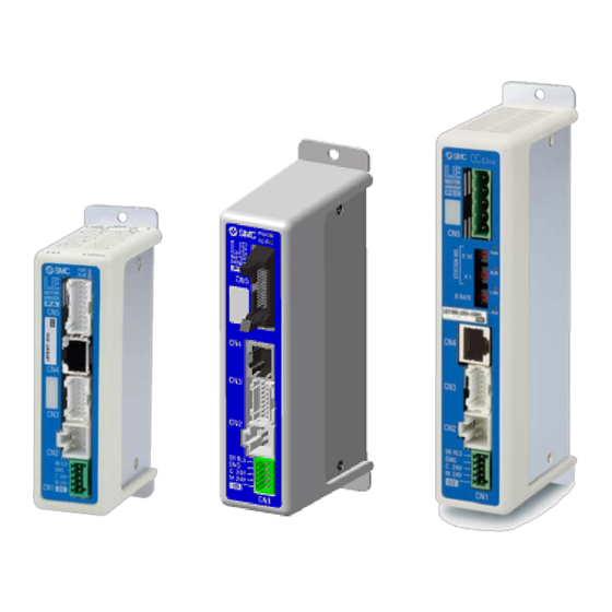
- Page 1 Doc. no. LEC-OM08802 PRODUCT NAME Data Writing Software for Blank Controller (LECP/A-BC) MODEL / Series/Product Number LEC-BCW This software is a tool which is required to use the blank controller. Please download the latest software from the SMC website http://www.smcworld.com/...
-
Page 2: Table Of Contents
Contents 1.Safety Instructions ................... 3 2. Outline of Product ................... 5 2.1 What is the data writing software (LEC-BCW)? ........5 2.2 What is the blank controller? ..............5 2.3 Required devices when using the data writing software ....5 2.4 System structure when using the data writing software .... - Page 3 (3)How to use SV No. check “Read SV Number” buttton... 31 4.5 Software completion ................31 5. Alarm ...................... 32 7. Wiring of cables/Common precautions ..........34 8. Electric actuators/Common precautions ..........35 8.1 Design and selection ................35 8.2 Mounting ....................36 8.3 Handling ....................
-
Page 4: Safety Instructions
LEC-BCW/ Data writing software 1.Safety Instructions These safety instructions are intended to prevent hazardous situations and/or equipment damage. These instructions indicate the level of potential danger with the labels of “Caution,” “Warning” or “Danger.” They are all important notes for safety and must be followed in addition to International Standards (ISO/IEC), Japan Industrial Standards (JIS)*1) and other safety regulations*2). - Page 5 LEC-BCW/ Data writing software Safety Instructions Caution The product is provided for use in manufacturing industries. The product herein described is basically provided for peaceful use in manufacturing industries. If use of this product in other industries is being condered, consult SMC beforehand and exchange specifications or make a contract if necessary.
-
Page 6: Outline Of Product
2. Outline of Product 2.1 What is the data writing software (LEC-BCW)? This software is a tool which writes the parameters and step data of a specified actuator to the blank controller of the motor controller series (LECP/A series). It is possible to write default parameters and step data to the controller models below. Step Motor Controller LECP6*-BC Servo Motor Controller... -
Page 7: System Structure When Using The Data Writing Software
2.4 System structure when using the data writing software The system strucure when using the data writing software is described below. Controller LECP/A*-BC Peronal computer To USB port To CN4 ● ● Commnication cable USB cable (A-miniB type) LEC-W2-C LEC-W2-U These cables are included in the controller setting kit LEC-W2. -
Page 8: Preparation
3. Preparation 3.1 Procedure before use (1) Preparation of devices Prepare required devices with reference to 2.3 Required devices when using the data writing software. Note) When the communication cable and USB cable are used with the PC for the first time, a driver needs to be installed. -
Page 9: Installation
3.2 Installation (1)Save the compressed file of the downloaded application from SMC website (http://www.smcworld.com/) to an arbitrary location and decompress it. (2)Copy the decompressed application folder to an arbitrary location. (3)Installation is complete after confirming that the folder and file shown below are included in the copied application folder. -
Page 10: Function
4. Function 4.1 List of functions Function Description Writing function by selecting Specify the applicable actuator based on the specifications ACT (actuator) and product part numbers, and program the actuator data into the connected controller. Writing function by specifying Specify the backup file (bkp) previously created with the files backup function, and program the content into the connected controller. -
Page 11: Software Start-Up
4.2 Software start-up This software starts up when double clicking the "LEC-BCW.exe" file. At starts up, a software license agreement window appears, which confirms the use of this software (see the image below). After clicking the "Agree" button, the communication setting window is displayed. Refer to 4.3 Communication setting for how to set communication. -
Page 12: Communication Settings
4.3 Communication settings When communication is established with the controller, the communication setting window appears. Communication check can be selected from "auto" or "manual" method (1)Communication settings window 1. Communication port 2. Communication method 3. Controller ID 4. Communication speed 5. - Page 13 Communication speed For "manual" communication confirmation, the communication speed which has been set in the connected controller can be selected. The range of communication speeds are 9600, 19200, 38400, 57600, 115200 and 230400[bps]. Manually set ID and communication speed are initialized to the Setting initialization button default values that are stated below.
- Page 14 <How to Confirm the Communication Port Number> Using the start menu, open the "Control panel”, then select "Hardware and sound" and then select "Device manager". (This start-up method is an example for Window®7. Please start the device manager in accordance with the operation environment of the PC.) Confirm the COM port number of the SMC Serial Port from the devices displayed in "Port (COM &...
- Page 15 c) Click the "Check communication" button and confirm whether the set communication method establishes communication to the controller. Once the communication is acceptable, the window below is displayed, and controller ID and communication speed during communication are displayed. Click the "OK" button after confirmation When communication is established.
- Page 16 If the controller connected is not the blank controller (LEC[]-BC), the window below is displayed. When the "OK" button is clicked, the window is returned to the communication setting screen. Caution This software is only applicable to the blank controllers (LEC*-BC). It is not possible to write into the any controllers models other than the blank controllers.
-
Page 17: Main Menu
4.4 Main menu "Func (function)", "Comm (communication) setting" and "Help" can be selected on the main menu. On "Func"tab, the data writing by selecting ACT or selecting file functions and the "Backup" function can be selected. (1)Main menu window 1.Function selecting tabs 2.Writing button by 3.Writing button by... - Page 18 (2)Name and function Description Function "Func", "Comm setting" and "Help" windows can be selected. Function selecting Refer to 4.3 Communication setting for how to set up tabs communication to the controller. Refer to 4.4 Help for "help". Writing button by Select the product number of the actuator based on the selecting ACT specifications and part number of the actuator.
-
Page 19: Write By Selecting Act(Actuator)
4.4.1 Write by selecting ACT(actuator) Writing function by selecting ACT (actuator) is to specify the product No. of the actuator by setting the actuator specifications and controller model and condition, and write the specific data of the applicable actuator to the controller. Caution The actuator specific data written to the blank controller and the actuator model should be identical. -
Page 20: Name And Function
(2)Name and function Description Function Search method Actuators can be selected from "search on condition" or "search from product No.". ・Search on condition :Select the "ACT series", "Controller", "Dir. of installing motor ", "Lead" and "Stroke" of the actuator to which parameter or step data is written, and search the product No. -
Page 21: How To Use Writing Function By Selecting Act (Actuator)
Written data Set the content written to the controller. The content can be selected from three options below. ・Parameters and step data ・Parameter only ・Step data only Return button Return to the main menu. Writing preparation The data compatible with the set actuator and controller completion button has been written to the controller. - Page 22 c) Click the "Seek" button. If a result applicable to the selected actuator is hit, the actuator product no. is displayed in the "Seeking product No. of ACT". Click the "Seeking product No. of ACT" list button below and select the product No. of the actuator to which parameter or step data is to be written.
- Page 23 e) Click the "Written data"list button and select the data to be written to the controller. f) Click the Writing preparation completion “NEXT” button. Note) Be sure to backup any previously programmed controller data before writing the data to the controller. Refer to 4.4.3 Backup for how to backup the data.
- Page 24 When the writing of data is complete, the Writing completed window is displayed. In this case, click the "OK" button and complete the data writing operation. It is recommended to write the product part number of the actuator on the controller after data writing operation is completed.
-
Page 25: Writing By Specifying Files
4.4.2 Writing by specifying files In the writing function by specifying files, the contents of the specified data file are written to the connected controller. The data file that can be specified must be generated by the "Backup" function. Window 1.File name selected 2.Reference button of the selected file... -
Page 26: How To Use Writing Function By Specifying Files
(3)How to use writing function by specifying files a) When clicking "Ref." button, "Open" window is displayed. b) Select the backup file (data file with bkp extension) prepared by the backup function (refer to 4.4.3 Backup) and click the "Open" button. In the window example below, (BackupFile.bkp) is selected. - Page 27 d) When clicking the writing preparation completion“Next” button, the check window is displayed. Caution Be sure to backup any previously programmed data in the controller before writing the data. Refer to 4.4.3 Backup for how to backup. e) Verify the actuator product No., SV No. and written content data are correct. If the data is correct, cilck the "Write"...
- Page 28 When the writing of data is complete, the Writing completed window is displayed. In this case, click the "OK" button and complete the data writing operation. Caution Do not remove the communication cable until the PWR light on the controller stops blinking.
-
Page 29: Backup
4.4.3 Backup In the backup function, read the data from the connected controller and prepare a backup file. A backup file generated by this function can be written to a connected controller by specifying it in the "Writing by selecting files" function (Refer to 4.4.2 Writing by specifying files). (1)Backup window 1.Backup file 2.Reference button... - Page 30 b) Select a location where the backup file is to be saved, input an arbitrary file name and click the "Save" button. e) Click the "Backup" button. When the backup is complete, the backup completed window is displayed. In this case, click the "OK" button and complete the backup operation. When backup completed If an error occurs during backup, an "Error"...
-
Page 31: Help
4.4.4 Help On the help window, software version, version of the referenced data file and SV No. of the connected controller can be confirmed. At the same time, the referenced data file can be updated. (1)Help screen 5.Update button 1.Software version 2.Data version 3.SV No. -
Page 32: How To Use Sv No. Check "Read Sv Number" Buttton
(3)How to use SV No. check “Read SV Number” buttton The SV No. of the connected controller is read by clicking the "Read SV Number" button, and is displayed as "SV No.". If an error occurs, the “LE Data Downloader”error window will be displayed as shown below. this case, click the "OK"... -
Page 33: Alarm
5. Alarm If an error occurs while the the software is used, an alarm window appears. The alarm name and countermeasures are displayed. List of alarms Alarm name Countermeasure Communication error Communication with the controller cannot be established. Please check the following points. (1)The power supply of motor controller (LEC) has been turned on. - Page 34 List of warnings Alarm name Countermeasure This is not a blank The connected controller is not a blank controller.。 controller. When writing the data, prepare a blank controller. Backup function can only be used. you want to execute backup?) The controller and the The model data and SV No.
-
Page 35: Wiring Of Cables/Common Precautions
7. Wiring of cables/Common precautions ! Warning 1. Adjusting, mounting or wiring change should never be done before shutting off the power supply to the product. Electrical shock, malfunction and damaged can result. Never disassemble the cable. Use only specified cables. Never connect or disconnect the cable or connector with power on. -
Page 36: Electric Actuators/Common Precautions
8. Electric actuators/Common precautions 8.1 Design and selection ! Warning 1. Be sure to read the Operation Manual (this manual and the one for the controller: LEC series). Handling or usage/operation other than that specified in the Operation Manual may lead to breakage and operation failure of the product. -
Page 37: Mounting
Do not use the product in applications where excessive external force or impact force is applied to it. The product can be damaged. Each component that includes motor is made with accurate tolerance. So even slightly deformed or miss-alignment of component may lead operation failure of the product. Rerutning to origin cannot be done during the operation. -
Page 38: Handling
8.3 Handling ! Warning Do not touch the motor while in operation. The surface temperature of the motor can increase to approx. 90oC to 100oC due to operating conditions. This temperature increase may also be caused by energizing alone. As it may cause burns, do not touch the motor when in operation. -
Page 39: Operating Environment
[Unpackaging] ! Caution 1. Check the received product is as ordered. If a different product is installed from the one ordered, injury or damage can result. 8.4 Operating environment ! Warning Avoid use in the following environments. a. Locations where a large amount of dusts and cutting chips are airborne. b. -
Page 40: Maintenance
8.5 Maintenance ! Warning Do not disassemble or repair the product. Fire or electric shock can result. 2. Before modifying or checking the wiring, the voltage should be checked with a tester 5 minutes after the power supply is turned off. Electrical shock can result. -
Page 41: Precautions:controller And Its Peripheral Devices Electric Actuators/Common Precautions
Precautions:Controller and its peripheral devices Electric actuators/Common precautions 9.1 Design and selection Warning 1. Be sure to apply the specified voltage. Otherwise, a malfunction and breakage of the controller may be caused. If the applied voltage is lower than the specified, it is possible that the load cannot be moved due to an internal voltage drop. -
Page 42: Installation
9. Do not use in an area where dust, powder dust, water or oil is in the air. It will cause failure or malfunction. 10. Do not use in an area where a magnetic field is generated. It will cause failure or malfunction. 11. -
Page 43: Wiring Of Cables/Common Precautions
9.4 Wiring of cables/Common precautions Warning 1. Do not apply any excessive force to cables by repeated bending, tensioning or placing a heavy object on the cables. It may cause an electric shock, fire, or breaking of wire. 2. Connect wires and cables correctly. Incorrect wiring could break he controller or its peripheral devices depending on the seriousness. -
Page 44: Maintenace
3. Grounding should be performed near the unit as much as possible to shorten the grounding distance. 4. In the unlikely event that malfunction is caused by the ground, it may be disconnected. 9.7 Maintenace Warning 1. Perform a maintenance check periodically Confirm wiring and screws are not loose. - Page 45 Tel: + 81 3 5207 8249 Fax: +81 3 5298 5362 http://www.smcworld.com Note: Specifications are subject to change without prior notice and any obligation on the part of the manufacturer. © 2015 SMC Corporation All Rights Reserved. - 44 -...
Need help?
Do you have a question about the LEC-BCW Series and is the answer not in the manual?
Questions and answers