Toro Workman HDX-D Operator's Manual
Hide thumbs
Also See for Workman HDX-D:
- Service manual (318 pages) ,
- Operator's manual (60 pages) ,
- Operator's manual (60 pages)
Table of Contents
Advertisement
Quick Links
Advertisement
Table of Contents

Related Manuals for Toro Workman HDX-D


Summary of Contents for Toro Workman HDX-D
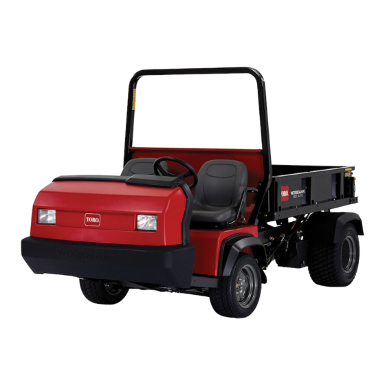
- Page 1 Workman ® HDX-D Utility Vehicle Model No. 07385—Serial No. 414959294 and Up Model No. 07385TC—Serial No. 415000000 and Up Model No. 07387—Serial No. 413000000 and Up Model No. 07387TC—Serial No. 414900000 and Up *3463-676* Register at www.Toro.com. Original Instructions (EN)
- Page 2 Whenever you need service, genuine Toro parts, or g000502 additional information, contact an Authorized Service Figure 2 Distributor or Toro Customer Service and have the Safety-alert symbol model and serial numbers of your product ready.
-
Page 3: Table Of Contents
Contents Inspecting Fuel Lines and Connections..... 44 Electrical System Maintenance ......45 Electrical System Safety ........45 Safety ............... 4 Servicing the Fuses .......... 45 General Safety ........... 4 Jump-Starting the Machine....... 45 Safety and Instructional Decals ......5 Servicing the Battery......... 46 Setup .............. -
Page 4: Safety
Safety This machine has been designed in accordance with the requirements of SAE J2258 (Nov 2016). General Safety This product is capable of causing personal injury. Always follow all safety instructions to avoid serious personal injury. • Read and understand the contents of this Operator’s Manual before you start the machine. -
Page 5: Safety And Instructional Decals
Safety and Instructional Decals Safety decals and instructions are easily visible to the operator and are located near any area of potential danger. Replace any decal that is damaged or missing. decalbatterysymbols Battery Symbols Some or all of these symbols are on your battery. 1. - Page 6 decal105-4215 105-4215 decal106-2355 1. Warning—avoid pinch points. 106-2355 1. Slow 3. Transmission—third high; no fast speed 2. Fast decal106-2377 106-2377 1. Locked 8. Warning—read the Operator's Manual. 2. Differential lock 9. Entanglement hazard, shaft—keep bystanders out of the operating area. 3.
- Page 7 decal106-6755 106-6755 1. Engine coolant under 3. Warning—do not touch the pressure. hot surface. 2. Explosion hazard—read 4. Warning—read the the Operator's Manual. Operator's Manual. decal106-7767 106-7767 1. Warning—read the Operator's Manual; avoid tipping the machine; wear the seat belt; lean away from the direction the machine is tipping.
- Page 8 decal115-2282 115-2282 1. Warning—read the Operator's Manual. 2. Warning—stay away from moving parts; keep all guards and shields in place. 3. Crushing hazard—keep bystanders out of the operating area; do not carry passengers in the cargo bed; keep arms and legs inside of the vehicle at all times;...
- Page 9 decal121-6287 121-6287 decal121-6286 121-6286 1. Fill the reservoir with engine coolant to the bottom of the filler neck. 1. Check the coolant level 2. Do not open or add coolant to the radiator; doing so daily before use of the machine. Read introduces air into the the Operator's Manual system and results in...
- Page 10 decal139-3341 139-3341 1. Tank 3. Pressure 2. Warning—the hydraulic-fluid pressure is 138 bar (2,000 psi). decal145-2276 145-2276 1. Engine—stop 3. Engine—start 2. Engine—run...
- Page 11 decal145-2282 145-2282 1. Power point decal145-2286 145-2286 1. Power outlet (10 A) 5. Lights, brake (15 A) 2. Switched power (10 A) 6. Hazard (10 A) 3. Fuel pump, supervisor 7. 4WD, transmission (10 A) switch (10 A) 4. Horn, power point (15 A)
-
Page 12: Setup
Setup Loose Parts Use the chart below to verify that all parts have been shipped. Procedure Description Qty. Install the steering wheel (TC models Steering wheel only). Roll bar Install the roll bar. Flange-head bolt (1/2 x 1-1/4 inches) – No parts required Check the fluid levels and tire pressure. -
Page 13: Installing The Roll Bar
Installing the Roll Bar Checking the Fluid Levels and Tire Pressure Parts needed for this procedure: Roll bar No Parts Required Flange-head bolt (1/2 x 1-1/4 inches) Procedure Procedure Check the engine-oil level before and after you first start the engine; refer to Checking the Apply medium-grade (service-removable) Engine-Oil Level (page... -
Page 14: Product Overview
Product Overview Controls Become familiar with all the controls before you start the engine and operate the machine. Control Panel g381123 Figure 5 1. Horn switch 5. Display 2. Light switch 6. Power point 3. 4-wheel drive switch (4-wheel drive models only) 7. - Page 15 Display g347586 Figure 6 1. Fuel gauge 6. Check-engine indicator 2. Tachometer/engine speed (rpm) 7. Tachometer-speedometer location change button/Speedometer conversion button 3. Speedometer (km/h or mph) 8. Hour meter 4. Coolant-temperature gauge and light 9. Oil-pressure-warning light 5. Glow-plug indicator (diesel machines only) 10.
- Page 16 Gear-Shift Lever Fully press the clutch pedal and move the shift lever (Figure 8) into the desired gear selection. A diagram of the shift pattern is shown below. g009160 Figure 8 g350294 Figure 9 1. Parking-brake lever 5. High-low range shifter Important: Do not shift the transaxle to the 2.
- Page 17 Hydraulic-Lift Lock Supervisor Switch The hydraulic-lift lock secures the lift lever, so that the Move the supervisor switch (Figure 5) to the SLOW hydraulic cylinders do not operate when the machine position and remove the key. The supervisor switch is not equipped with a bed (Figure 9).
- Page 18 Glow-Plug Indicator Light High-Flow Hydraulics Switch TC Models Only The glow-plug indicator light (Figure 6) illuminates red when the glow plugs are activated. Turn on the switch to activate the high-flow hydraulics Important: The glow-plug indicator light turns (Figure on for an additional 15 seconds when the switch returns to the S position.
- Page 19 Passenger Handhold The passenger handhold is located on the dashboard (Figure 10). g009815 Figure 10 1. Passenger handhold 2. Storage compartment Seat-Adjustment Lever You can adjust the seat forward and rearward for your comfort (Figure 11). g021227 Figure 11 1. Seat-adjustment lever...
-
Page 20: Specifications
191 cm (75 inches) to the top of the roll bar Attachments/Accessories A selection of Toro approved attachments and accessories is available for use with the machine to enhance and expand its capabilities. Contact your Authorized Service Dealer or Distributor or go to www.Toro.com... -
Page 21: Before Operation
Checking the Tire Pressure Operation Service Interval: Before each use or daily Before Operation Front tires air pressure specification: 220 kPa (32 psi) Before Operation Safety Rear tires air pressure specification: 124 kPa (18 psi) General Safety Important: Check the tire pressure frequently •... -
Page 22: Adding Fuel
Adding Fuel Use only clean, fresh diesel fuel or biodiesel fuels with low (<500 ppm) or ultra-low (<15 ppm) sulfur content. The minimum cetane rating should be 40. Purchase fuel in quantities that can be used within 180 days to ensure fuel freshness. •... -
Page 23: Checking The Safety-Interlock System
Checking the During Operation Safety-Interlock System During Operation Safety Service Interval: Before each use or daily The purpose of the safety-interlock system is to General Safety prevent the engine from cranking or starting, unless • The owner/operator can prevent and is responsible you press the clutch pedal. - Page 24 • Use accessories and attachments approved by the machine to tip or roll over. Do not engage the The Toro® Company only. brakes suddenly when rolling rearward, as this may cause the machine to overturn. Rollover Protection System...
-
Page 25: Operating The Cargo Bed
the cargo bed and/or towing a trailer; refer to Specifications (page 20). • Distribute the load in the cargo bed evenly to improve the stability and control of the machine. • Before dumping, ensure that there is no one behind the machine. •... -
Page 26: Starting The Engine
result. If engine fails to start after 10 seconds, turn the key to the O position. Check the controls and starting procedure, wait 10 additional seconds, and repeat the starting operation. Engaging the 4-Wheel Drive 4-Wheel Drive Models Only To enable automatic 4-Wheel Drive, press the top of the rocker switch into the 4 position (Figure... -
Page 27: Driving The Machine
Driving the Machine Using the Differential Lock Disengage the parking brake. WARNING Fully press the clutch pedal. Tipping or rolling the machine on a hill will Move the gear-shift lever to first gear. cause serious injury. Release the clutch pedal smoothly while •... -
Page 28: Using The Hydraulic Control
Using the Hydraulic Control Using the Hydraulic Bed-Lift Lever to Control Hydraulic Attachments The hydraulic control supplies hydraulic power from • the machine pump whenever the engine runs. You Position can use the power through the quick couplers at the This is the normal position for the control valve rear of the machine. - Page 29 Troubleshooting the Hydraulic This position is similar to the L OWER QUICK ). It also directs hydraulic fluid COUPLER POSITION Control to quick coupler B, except that the lever is held in this position by a detent lever in the control panel. •...
-
Page 30: After Operation
After Operation After Operation Safety General Safety • Before you leave the operating position, do the following: – Park the machine on a level surface. g009820 – Shift the transmission to the N position. EUTRAL Figure 19 – Engage the parking brake. 1. -
Page 31: Towing A Trailer
Towing a Trailer The machine is capable of pulling trailers and attachments of greater weight than the machine itself. Several types of tow hitches are available for the machine, depending on your application. Contact your Authorized Service Dealer for details. When equipped with a tow hitch bolted onto the rear axle tube, your machine can tow trailers or attachments with a maximum gross trailer weight... -
Page 32: Maintenance
Such use – Wait for all movement to stop. could void the product warranty of The Toro® • Allow the machine to cool before adjusting, Company. -
Page 33: Recommended Maintenance Schedule(S)
Recommended Maintenance Schedule(s) Maintenance Service Maintenance Procedure Interval • Torque the front and rear wheel lug nuts. After the first 2 hours • Check the adjustment of the shift cables. • Torque the front and rear wheel lug nuts. • Check the adjustment of the parking brake. After the first 10 hours •... - Page 34 • If you are using the recommended hydraulic fluid, change the high-flow hydraulic Every 2,000 hours fluid. Note: Download a copy of the electrical schematic by visiting www.Toro.com and searching for your machine from the Manuals link on the home page. Important: Refer to your engine owner’s manual for additional maintenance procedures.
-
Page 35: Maintaining The Machine Under Special Operating Conditions
Maintaining the Machine under Special Operating Conditions Important: If the machine is subjected to any of the conditions listed below, perform maintenance twice as frequently: • Desert operation • Cold climate operation—below 10°C (50°F) • Trailer towing • Frequent operation in dusty conditions •... -
Page 36: Removing The Full Bed
Removing the Full Bed Start the engine, engage the hydraulic-lift lever, and lower the bed until the cylinders are loose in the slots. Release the lift lever and shut off the engine. Remove the lynch pins from the outer ends of the cylinder rod clevis pins (Figure 23). -
Page 37: Installing The Full Bed
Installing the Full Bed Note: If you are installing the bed sides on the flat bed, it is easier to install them before installing the bed on the machine. Ensure that the rear pivot plates are bolted to the bed frame/channel so that the lower end angles to the rear (Figure 24). -
Page 38: Raising The Machine
Raising the Machine DANGER A machine on a jack may be unstable and slip off the jack, injuring anyone beneath it. • Do not start the machine while the machine is on a jack, as the engine vibration or wheel movement could cause the machine to slip off the jack. -
Page 39: Lubrication
Lubrication Pivot the top of the hood forward and unplug the wire connectors from the headlights (Figure 28). Remove the hood. Greasing the Bearings and Bushings Installing the Hood Connect the lights. Service Interval: Every 100 hours (lubricate more frequently in heavy-duty Insert the top mounting tabs into the frame slots applications). - Page 40 • Brake (1); refer to Figure 31 g002394 g010571 Figure 31 Figure 30 • U-joint (18); refer to Figure 32 • Clutch (1); refer to Figure 31 • • Accelerator (1); refer to Figure 31 4-wheel drive shaft (3); refer to Figure 32 g010359 Figure 32...
-
Page 41: Engine Maintenance
Engine Maintenance Inspect the new filter for damage by looking into the filter while shining a bright light on the outside of the filter. Engine Safety Note: Holes in the filter appear as bright spots. Inspect the element for tears, an oily •... -
Page 42: Servicing The Engine Oil
Servicing the Engine Oil Note: Change the oil more frequently when operating conditions are extremely dusty or sandy. Note: Dispose of the used engine oil and oil filter at a certified recycling center. Engine-Oil Specifications Oil Type: Detergent engine oil (API SJ or higher) Crankcase Capacity: 3.2 L (3.4 US qt) when the filter is changed g028637... - Page 43 Add the specified oil to the crankcase. Responding to a Check-Engine Light Note: Engine-fault code information can be accessed by your Toro commercial products service staff only. Park the machine on a level surface. Engage the parking brake. g002373 Figure 36 Shut off the engine and remove the key.
-
Page 44: Fuel System Maintenance
Changing the Fuel Filter Fuel System Maintenance Service Interval: Every 400 hours—Replace the fuel filter. Drain the water from the water separator; refer Servicing the Fuel Draining the Fuel Filter/Water Separator (page 44). Filter/Water Separator Clean the area where the filter mounts (Figure 38). -
Page 45: Electrical System Maintenance
Electrical System Maintenance Electrical System Safety • Disconnect the battery before repairing the machine. Disconnect the negative terminal first and the positive last. Connect the positive terminal first and the negative last. • Charge the battery in an open, well-ventilated area, away from sparks and flames. -
Page 46: Servicing The Battery
Start the engine in the machine providing the jump-start. Note: Let it run for a few minutes, then start your engine. Remove the negative jumper cable first from your engine, then the battery in the other machine. Install the battery cover to the battery base. Servicing the Battery Service Interval: Every 50 hours—Check the battery-fluid level (every 30 days if... -
Page 47: Drive System Maintenance
Changing the Front Drive System Differential Oil Maintenance 4-Wheel Drive Models Only Checking the Front Service Interval: Every 800 hours (4-wheel drive models only). Differential-Oil Level Differential oil specification: Mobil 424 hydraulic 4-Wheel Drive Models Only fluid Park the machine on a level surface. Service Interval: Every 100 hours/Monthly (whichever comes first)—Check Engage the parking brake. -
Page 48: Adjusting The Shift Cables
Adjusting the Shift Cables Adjusting the High-Low Cable Service Interval: After the first 10 hours Every 200 hours Service Interval: Every 200 hours Move the shift lever to the N position. EUTRAL Remove the clevis pin securing the high-low cable to the transaxle (Figure 44). -
Page 49: Inspecting The Tires
Inspecting the Tires Checking the Front Wheel Alignment Service Interval: Every 100 hours Front tires air pressure specification: 220 kPa (32 Service Interval: Every 400 hours/Yearly (whichever psi) comes first) Rear tires air pressure specification: 124 kPa (18 Ensure that the tire pressures are correct before psi) checking the front wheel alignment;... -
Page 50: Torquing The Wheel Lug Nuts
Torquing the Wheel Lug Nuts Service Interval: After the first 2 hours After the first 10 hours Every 200 hours Wheel lug nut torque specification: 109 to 122 N∙m (80 to 90 ft-lb) Torque the lug nuts at the front and rear wheels in a crossing pattern as shown in Figure 50 to the... -
Page 51: Cooling System Maintenance
Cooling System Shut off the engine and remove the key. Check the coolant level inside the reserve tank. Maintenance Cooling System Safety • Swallowing engine coolant can cause poisoning; keep out of reach from children and pets. • Discharge of hot, pressurized coolant or touching a hot radiator and surrounding parts can cause severe burns. -
Page 52: Removing Debris From The Cooling System
Shut off the engine and remove the key. Coolant type: a 50/50 solution of water and Clean the engine area thoroughly of all debris. permanent ethylene-glycol antifreeze Unlatch and remove the radiator screen from the Contact your authorized Toro distributor. front of the radiator (Figure 52). g010315 Figure 52 1. -
Page 53: Brake Maintenance
Brake Maintenance Checking the Brake-Fluid Level Service Interval: Before each use or daily—Check the brake-fluid level. Check the brake-fluid level before you first start the engine. Every 1,000 hours/Every 2 years (whichever g002379 comes first)—Change the brake fluid. Figure 55 Brake-fluid type: DOT 3 1. -
Page 54: Adjusting The Brake Pedal
Adjusting the Brake Pedal Service Interval: Every 200 hours Note: Remove the font hood to ease the adjustment procedure. Remove the cotter pin and clevis pin securing the master cylinder yoke to the brake-pedal g033488 Figure 57 pivot (Figure 58). 1. -
Page 55: Belt Maintenance
Belt Maintenance Adjusting the Alternator Belt Service Interval: After the first 10 hours—Check the condition and tension of the alternator belt. Every 200 hours—Check the condition and tension of the alternator belt. g036549 Figure 59 Raise the bed and position the safety support on the extended lift cylinder to secure the bed. -
Page 56: Controls System Maintenance
Controls System Maintenance Adjusting the Clutch Pedal Service Interval: Every 200 hours Note: You can adjust the clutch-pedal cable at the bell housing or at the clutch-pedal pivot. You can remove the front hood to easily access to the pedal g009276 pivot. -
Page 57: Adjusting The Accelerator Pedal
Adjusting the Accelerator Hydraulic System Pedal Maintenance Park the machine on a level surface, engage the parking brake, shut off the engine, and remove Hydraulic System Safety the key. • Seek immediate medical attention if fluid is injected Adjust the ball joint on the accelerator cable (Figure 64) to allow 2.54 to 6.35 mm (0.100 to into skin. - Page 58 g009623 Figure 67 1. Hydraulic reservoir 2. Drain plug g002376 Figure 66 Note the orientation of the hydraulic hose and 1. Dipstick 90° fitting connected to the strainer on the side of the reservoir (Figure 68). Unscrew the dipstick from the top of the Remove the hydraulic hose and 90°...
- Page 59 Check the hydraulic-fluid level and replenish it, if required. Important: Use only the hydraulic fluid specified. Other fluids could damage the system. Replacing the Hydraulic Filter Service Interval: After the first 10 hours—Replace the hydraulic filter. Every 800 hours—Replace the hydraulic filter. Important: Use of any other filter may void the warranty on some components.
-
Page 60: Servicing The High-Flow Hydraulic System
A machine using the recommended replacement fluid requires less frequent fluid and filter changes. Alternative fluids: If Toro PX Extended Life Hydraulic Fluid is not available, you may use another conventional, petroleum-based hydraulic fluid having specifications that fall within the listed range for all the following material properties and that it meets industry standards. -
Page 61: Raising The Cargo Bed In An Emergency
Changing the High-Flow Hydraulic Raising the Cargo Bed in Fluid and Filter an Emergency TC Models Only The cargo bed can be raised in an emergency without Service Interval: Every 1,000 hours—If you are starting the engine by cranking starter or by jumping using the recommended hydraulic the hydraulic system. - Page 62 g019543 Figure 73 1. Jumper hoses Keep all bystanders away from the machines. Start the second machine and move the lift lever to the raise position, which raises the disabled g009822 Figure 71 cargo bed. 1. Quick-coupler hose A Move the hydraulic-lift lever to the N EUTRAL position, and engage the lift-lever lock.
-
Page 63: Cleaning
Cleaning Washing the Machine Wash the machine as needed using water alone or with a mild detergent. You may use a rag when washing the machine. Important: Do not use brackish or reclaimed water to clean the machine. Important: Do not use power-washing equipment to wash the machine. -
Page 64: Storage
Storage A fully charged battery maintains its charge for about 50 days at temperatures lower than 4°C (40°F). If the temperatures will be Storage Safety above 4°C (40°F), check the water level in the battery and charge it every 30 days. •... -
Page 65: Troubleshooting
Troubleshooting Problem Possible Cause Corrective Action The quick couplers are difficult to 1. The hydraulic pressure not relieved 1. Shut off the engine, move the connector disconnect. (the quick coupler is under pressure). hydraulic-lift lever forward and backward several times, and connect the quick couplers for the fittings in the auxiliary hydraulic panel. - Page 66 While the exposure from Toro products may be negligible or well within the “no significant risk” range, out of an abundance of caution, Toro has elected to provide the Prop 65 warnings. Moreover, if Toro does not provide these...
- Page 67 The Toro Company (“Toro”) respects your privacy. When you purchase our products, we may collect certain personal information about you, either directly from you or through your local Toro company or dealer. Toro uses this information to fulfil contractual obligations - such as to register your warranty, process your warranty claim or to contact you in the event of a product recall - and for legitimate business purposes - such as to gauge customer satisfaction, improve our products or provide you with product information which may be of interest.
- Page 68 Countries Other than the United States or Canada Customers who have purchased Toro products exported from the United States or Canada should contact their Toro Distributor (Dealer) to obtain guarantee policies for your country, province, or state. If for any reason you are dissatisfied with your Distributor's service or have difficulty obtaining guarantee information, contact your Authorized Toro Service Center.
Need help?
Do you have a question about the Workman HDX-D and is the answer not in the manual?
Questions and answers