Table of Contents
Advertisement
Register at www.Toro.com.
Original Instructions (EN)
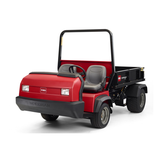
Workman
®
Model No. 07383—Serial No. 404350001 and Up
Model No. 07384—Serial No. 404350001 and Up
Model No. 07384TC—Serial No. 404350001 and Up
Model No. 07386—Serial No. 404350001 and Up
Model No. 07386TC—Serial No. 404350001 and Up
Form No. 3427-789 Rev A
HDX Utility Vehicle
*3427-789* A
Advertisement
Table of Contents

Related Manuals for Toro Workman HDX Series


Summary of Contents for Toro Workman HDX Series
- Page 1 Model No. 07383—Serial No. 404350001 and Up Model No. 07384—Serial No. 404350001 and Up Model No. 07384TC—Serial No. 404350001 and Up Model No. 07386—Serial No. 404350001 and Up Model No. 07386TC—Serial No. 404350001 and Up *3427-789* A Register at www.Toro.com. Original Instructions (EN)
- Page 2 Visit www.Toro.com for product safety and operation training materials, accessory information, help finding a dealer, or to register your product. Whenever you need service, genuine Toro parts, or additional information, contact an Authorized Service Distributor or Toro Customer Service and have the model and serial numbers of your product ready.
-
Page 3: Table Of Contents
Contents Inspecting the Carbon Canister Air Filter.............. 41 Replacing the Fuel Filter ........41 Safety ............... 4 Inspecting Fuel Lines and Connections..... 42 General Safety ........... 4 Electrical System Maintenance ......42 Safety and Instructional Decals ......5 Electrical System Safety ........42 Setup ...............11 Servicing the Fuses .......... -
Page 4: Safety
Safety This machine has been designed in accordance with the requirements of SAE J2258 (Nov 2016). General Safety This product is capable of causing personal injury. Always follow all safety instructions to avoid serious personal injury. • Read and understand the contents of this Operator’s Manual before you start the machine. -
Page 5: Safety And Instructional Decals
Safety and Instructional Decals Safety decals and instructions are easily visible to the operator and are located near any area of potential danger. Replace any decal that is damaged or missing. decalbatterysymbols Battery Symbols Some or all of these symbols are on your battery. 1. - Page 6 decal105-4215 105-4215 decal106-2355 1. Warning—avoid pinch points. 106-2355 1. Slow 3. Transmission—third high; no fast speed 2. Fast decal106-2353 106-2353 1. Electrical power point decal106-2377 106-2377 1. Locked 8. Warning—read the Operator's Manual. 2. Differential lock 9. Entanglement hazard, shaft—keep bystanders out of the operating area.
- Page 7 decal106-6755 106-6755 decal110-0806 110–0806 1. Engine coolant under 3. Warning—do not touch the pressure. hot surface. 2. Explosion hazard—read 4. Warning—read the the Operator's Manual. Operator's Manual. decal115-2047 115-2047 1. Warning—do not touch the hot surface. decal106-7767 106-7767 1. Warning—read the Operator's Manual; avoid tipping the machine;...
- Page 8 decal115-2282 115-2282 1. Warning—read the Operator's Manual. 2. Warning—stay away from moving parts; keep all guards and shields in place. 3. Crushing hazard—keep bystanders out of the operating area; do not carry passengers in the cargo bed; keep arms and legs inside of the vehicle at all times;...
- Page 9 decal121-6287 121-6287 decal121-6286 121-6286 1. Fill the reservoir with engine coolant to the bottom of the filler neck. 1. Check the coolant level 2. Do not open or add coolant to the radiator; doing so daily before use of the machine. Read introduces air into the the Operator's Manual system and results in...
- Page 10 decal137-9896 137-9896 1. 4x4 engage button decal138-3523 138-3523 1. Headlights 4. Engine—Run 2. Horn 5. Engine—Start 3. Engine—Shut off decal139-3341 139-3341 1. Tank 3. Pressure 2. Warning—the hydraulic-fluid pressure is 138 bar (2,000 psi).
-
Page 11: Setup
Setup Loose Parts Use the chart below to verify that all parts have been shipped. Procedure Description Qty. Install the steering wheel (TC models Steering wheel only). Roll bar Install the roll bar. Flange-head bolt (1/2 x 1-1/4 inches) – No parts required Check the fluid levels and tire pressure. -
Page 12: Checking The Fluid Levels And Tire Pressure
Installing the Roll Bar Checking the Fluid Levels and Tire Pressure Parts needed for this procedure: Roll bar No Parts Required Flange-head bolt (1/2 x 1-1/4 inches) Procedure Procedure Check the engine-oil level before and after you first start the engine; refer to Checking the Apply medium-grade (service-removable) Engine-Oil Level (page... -
Page 13: Product Overview
Product Overview Controls Note: Determine the left and right sides of the machine from the normal operating position. Control Panel g021226 Figure 6 1. Clutch pedal 3. Accelerator pedal 2. Brake pedal Clutch Pedal g240583 Figure 5 You must fully press the clutch pedal (Figure to disengage the clutch when starting the engine 1. - Page 14 Gear-Shift Lever Fully press the clutch pedal and move the shift lever (Figure 7) into the desired gear selection. A diagram of the shift pattern is shown below. g009160 Figure 7 g240581 Figure 8 Important: 1. Parking-brake lever Do not shift the transaxle to the 5.
- Page 15 Hydraulic-Lift Lock Hour Meter The hour meter indicates the total hours of machine The hydraulic-lift lock secures the lift lever, so that the hydraulic cylinders do not operate when the machine operation. The hour meter (Figure 5) starts to function is not equipped with a bed (Figure 8).
- Page 16 Charge Indicator Tachometer The tachometer displays the speed of the engine The charge indicator illuminates when the battery discharges. If the light illuminates during operation, (Figure 5 Figure stop the machine, shut off the engine, and check for Note: The white triangle indicates the desired engine possible causes, such as the alternator belt (Figure speed for 540 rpm PTO operation.
- Page 17 Passenger Handhold The passenger handhold is located on the dashboard (Figure 10). g009815 Figure 10 1. Passenger handhold 2. Storage compartment Seat-Adjustment Lever You can adjust the seat forward and rearward for your comfort (Figure 11). g021227 Figure 11 1. Seat-adjustment lever...
-
Page 18: Specifications
191 cm (75 inches) to top of ROPS Attachments/Accessories A selection of Toro approved attachments and accessories is available for use with the machine to enhance and expand its capabilities. Contact your Authorized Service Dealer or Distributor or go to www.Toro.com for a list of all approved attachments and accessories. -
Page 19: Before Operation
Performing Daily Operation Maintenance Note: Determine the left and right sides of the machine from the normal operating position. Service Interval: Before each use or daily Before starting the machine each day, perform the Before Operation Each Use/Daily procedures listed in Maintenance (page 29). -
Page 20: Adding Fuel
Adding Fuel • For best results, use only clean, fresh (less than 30 days old), unleaded gasoline with an cetane rating of 87 or higher ((R+M)/2 rating method). • Ethanol: Gasoline with up to 10% ethanol (gasohol) or 15% MTBE (methyl tertiary butyl ether) by volume is acceptable. -
Page 21: Checking The Safety-Interlock System
Checking the During Operation Safety-Interlock System During Operation Safety Service Interval: Before each use or daily The purpose of the safety-interlock system is to General Safety prevent the engine from cranking or starting, unless you press the clutch pedal. • The owner/operator can prevent and is responsible for accidents that may cause personal injury or CAUTION... - Page 22 Do not operate the machine when there is the risk of lightning. • Avoid starting, stopping, or turning the machine on a slope, especially with a load. Stopping while • Use accessories and attachments approved by going down a slope takes longer than stopping The Toro® Company only.
-
Page 23: Operating The Cargo Bed
on level ground. If you must stop the machine, CAUTION avoid sudden speed changes, which can cause If a load is concentrated near the back of the the machine to tip or roll over. Do not engage the cargo bed when you release the latches, the brakes suddenly when rolling rearward, as this bed may unexpectedly tip open, injuring you may cause the machine to overturn. -
Page 24: Starting The Engine
Engaging the 4-Wheel Drive 4-Wheel Drive Models Only To enable automatic 4-Wheel Drive, press the top of the rocker switch into the 4 position (Figure 17). g227244 Figure 17 1. 4x4 auto enable—on 2. 4x4 auto enable—off When the 4WD switch is on, the machine automatically engages the 4-wheel drive if the sensor detects the g026141 Figure 16... -
Page 25: Stopping The Machine
Note: Avoid long periods of engine idling. CAUTION Use the chart below to determine the ground Turning with the differential lock on can result speed of the machine at 3,600 rpm. in loss of machine control. Do not operate with differential lock on when making sharp Speed Speed Gear... - Page 26 Using the Hydraulic Bed-Lift Lever This position is similar to the L OWER QUICK ). It also directs hydraulic fluid COUPLER POSITION to Control Hydraulic Attachments to quick coupler B, except that the lever is held in • this position by a detent lever in the control panel. Position This allows hydraulic fluid to flow continuously to This is the normal position for the control valve...
-
Page 27: After Operation
Troubleshooting the Hydraulic After Operation Control • Difficulty in connecting or disconnecting quick After Operation Safety couplers. The pressure is not relieved (the quick coupler is General Safety under pressure). • Before you leave the operating position, do the • The power steering is turning with great following: difficulty or it is not turning at all. -
Page 28: Hauling The Machine
Hauling the Machine Towing the Machine • Use care when loading or unloading the machine In case of an emergency, you can tow the machine into a trailer or a truck. for a short distance; however, this is not the standard operating procedure. -
Page 29: Maintenance
Allow the machine to cool before adjusting, operation of the machine, performance, durability, servicing, cleaning, or storing it. or its use may result in injury or death. Such use could void the product warranty of The Toro® • Support the machine with jack stands whenever Company. -
Page 30: Recommended Maintenance Schedule(S)
Recommended Maintenance Schedule(s) Maintenance Service Maintenance Procedure Interval • Torque the front and rear wheel lug nuts. After the first 2 hours • Check the adjustment of the shift cables. • Torque the front and rear wheel lug nuts. • Check the adjustment of the parking brake. After the first 10 hours •... - Page 31 Every 2,000 hours fluid. Note: Download a free copy of the electrical schematic by visiting www.Toro.com and searching for your machine from the Manuals link on the home page. Important: Refer to your engine owner’s manual for additional maintenance procedures.
-
Page 32: Maintaining The Machine Under Special Operating Conditions
Maintaining the Machine under Special Operating Conditions Important: If the machine is subjected to any of the conditions listed below, perform maintenance twice as frequently: • Desert operation • Cold climate operation—below 10°C (50°F) • Trailer towing • Frequent operation in dusty conditions •... -
Page 33: Removing The Full Bed
Removing the Full Bed Start the engine, engage the hydraulic-lift lever, and lower the bed until the cylinders are loose in the slots. Release the lift lever and shut off the engine. Remove the lynch pins from the outer ends of the cylinder rod clevis pins (Figure 23). -
Page 34: Installing The Full Bed
Installing the Full Bed Note: If you are installing the bed sides on the flat bed, it is easier to install them before installing the bed on the machine. Ensure that the rear pivot plates are bolted to the bed frame/channel so that the lower end angles to the rear (Figure 24). -
Page 35: Raising The Machine
Raising the Machine DANGER A machine on a jack may be unstable and slip off the jack, injuring anyone beneath it. • Do not start the machine while the machine is on a jack, as the engine vibration or wheel movement could cause the machine to slip off the jack. -
Page 36: Lubrication
Lubrication Pivot the top of the hood forward and unplug the wire connectors from the headlights (Figure 28). Remove the hood. Greasing the Bearings and Bushings Installing the Hood Connect the lights. Service Interval: Every 100 hours (lubricate more frequently in heavy-duty Insert the top mounting tabs into the frame slots applications). - Page 37 g024682 Figure 31 g010571 Figure 30 • U-joint (18); refer to Figure 32 • 4-wheel drive shaft (3); refer to Figure 32 • Clutch (1); refer to Figure 31 • Brake (1); refer to Figure 31 g010359 Figure 32...
-
Page 38: Engine Maintenance
Engine Maintenance Inspect the new filter for damage by looking into the filter while shining a bright light on the outside of the filter. Engine Safety Note: Holes in the filter appear as bright spots. Inspect the element for tears, an oily •... -
Page 39: Servicing The Engine Oil
Servicing the Engine Oil Note: Change the oil more frequently when operating conditions are extremely dusty or sandy. Note: Dispose of the used engine oil and oil filter at a certified recycling center. Engine-Oil Specifications Oil Type: Detergent engine oil (API SJ or higher) Crankcase Capacity: 3.2 L (3.4 US qt) when the filter is changed g028637... - Page 40 Add the specified oil to the crankcase. Responding to a Check-Engine Light Note: Engine-fault code information can be accessed by your Toro commercial products service staff only. Park the machine on a level surface. Engage the parking brake. g002373 Figure 36 Shut off the engine and remove the key.
-
Page 41: Replacing The Spark Plugs
Replacing the Spark Plugs Fuel System Maintenance Service Interval: Every 100 hours/Yearly (whichever comes first) Replace the spark plugs if necessary. Inspecting the Carbon Type: NGK-R BKR5E (or equivalent) Canister Air Filter Air Gap: 0.81 mm (0.032 inch) Important: A cracked, fouled, dirty, or Service Interval: After the first 50 hours—Inspect the malfunctioning spark plug must be replaced. -
Page 42: Inspecting Fuel Lines And Connections
Electrical System Loosen the hose clamp and disconnect the fuel line from the fuel-pump cap (Figure 40). Maintenance Electrical System Safety • Disconnect the battery before repairing the machine. Disconnect the negative terminal first and the positive last. Connect the positive terminal first and the negative last. -
Page 43: Jump-Starting The Machine
decal115-7813 Figure 42 1. Power outlet (10 A) 5. Lights/brake (15 A) g010326 Figure 43 2. Switched power (10 A) 6. Hazard lights (10 A) 3. Fuel pump/supervisor 7. 4WD/transmission (10 A) 1. Battery cover switch (10 A) 4. Horn/power point (15 A) Connect a jumper cable between the positive posts of the 2 batteries (Figure... -
Page 44: Servicing The Battery
Drive System Start the engine in the machine providing the jump-start. Maintenance Note: Let it run for a few minutes, then start your engine. Checking the Front Remove the negative jumper cable first from your engine, then the battery in the other Differential-Oil Level machine. -
Page 45: Changing The Front Differential Oil
Changing the Front Inspecting the Constant-Velocity Boot Differential Oil 4-Wheel Drive Models Only 4-Wheel Drive Models Only Service Interval: Every 800 hours (4-wheel drive Service Interval: Every 200 hours (4-wheel drive models only). models only). Differential oil specification: Mobil 424 hydraulic Inspect the constant-velocity boot for cracks, holes, fluid or a loose clamp. -
Page 46: Adjusting The High-Low Cable
Adjusting the High-Low Inspecting the Tires Cable Service Interval: Every 100 hours Front tires air pressure specification: 220 kPa (32 Service Interval: Every 200 hours psi) Remove the clevis pin securing the high-low cable to the transaxle (Figure 46). Rear tires air pressure specification: 124 kPa (18 psi) Loosen the clevis jam nut and adjust the clevis so that the clevis hole aligns with the hole in the... -
Page 47: Checking The Front Wheel Alignment
Checking the Front Wheel Rotate the tie rod to move the front of the tire inward or outward to achieve the center Alignment to center distances from front to back. Tighten the tie rod jam nut when the Service Interval: Every 400 hours/Yearly (whichever adjustment is correct. -
Page 48: Cooling System Maintenance
Cooling System Shut off the engine and remove the key. Check the coolant level inside the reserve tank Maintenance (Figure 53). Note: The coolant should be up to the bottom Cooling System Safety of the filler neck when the engine is cold. •... -
Page 49: Removing Debris From The Cooling System
Removing Debris from the Install the cooler and screen to the radiator. Cooling System Changing the Engine Service Interval: Before each use or daily—Remove Coolant debris from the engine area and radiator. (Clean it more frequently in Service Interval: Every 1,000 hours/Every 2 years dirty conditions.) (whichever comes first) Park the machine on a level surface. -
Page 50: Brake Maintenance
Brake Maintenance Checking the Brake-Fluid Level Service Interval: Before each use or daily—Check the brake-fluid level. Check the brake-fluid level before you first start the engine. Every 1,000 hours/Every 2 years (whichever comes first)—Change the brake fluid. Brake-fluid type: DOT 3 Park the machine on a level surface. -
Page 51: Adjusting The Parking Brake
g033488 Figure 61 1. Knob 3. Parking-brake lever 2. Set screw g002379 Figure 59 Rotate the knob (Figure 61) until a force of 20 to 22 kg (45 to 50 lb) is required to actuate the 1. Brake-fluid reservoir lever. Tighten the set screw when finished (Figure 61). -
Page 52: Adjusting The Brake Pedal
Adjusting the Brake Pedal Service Interval: Every 200 hours Note: Remove the font hood to ease the adjustment procedure. Remove the cotter pin and clevis pin securing the master cylinder yoke to the brake-pedal pivot (Figure 62). g036549 Figure 63 1. -
Page 53: Belt Maintenance
Belt Maintenance Controls System Maintenance Adjusting the Alternator Belt Adjusting the Clutch Pedal Service Interval: After the first 10 hours—Check Service Interval: Every 200 hours the condition and tension of the Note: You can adjust the clutch-pedal cable at the alternator belt. -
Page 54: Adjusting The Accelerator Pedal
Adjusting the Accelerator Pedal Park the machine on a level surface, engage the parking brake, shut off the engine, and remove the key. Adjust the ball joint on the accelerator cable (Figure 68) to allow 2.54 to 6.35 mm (0.100 to 0.250 inch) of clearance between the accelerator pedal arm and the top of the diamond tread floor plate... -
Page 55: Converting The Speedometer
Converting the Hydraulic System Speedometer Maintenance You can convert the speedometer from mph to km/h or km/h to mph. Hydraulic System Safety Park the machine on a level surface, engage the • Seek immediate medical attention if fluid is injected parking brake, shut off the engine, and remove into skin. - Page 56 g009623 Figure 71 1. Hydraulic reservoir 2. Drain plug g002376 Figure 70 Note the orientation of the hydraulic hose and 1. Dipstick 90° fitting connected to the strainer on the side of the reservoir (Figure 72). Unscrew the dipstick from the top of the Remove the hydraulic hose and 90°...
- Page 57 Check the hydraulic-fluid level and replenish it, if required. Important: Use only the hydraulic fluid specified. Other fluids could damage the system. Replacing the Hydraulic Filter Service Interval: After the first 10 hours—Replace the hydraulic filter. Every 800 hours—Replace the hydraulic filter. Important: Use of any other filter may void the warranty on some components.
-
Page 58: Servicing The High-Flow Hydraulic System
A machine using the recommended replacement fluid requires less frequent fluid and filter changes. Alternative fluids: If Toro PX Extended Life Hydraulic Fluid is not available, you may use another conventional, petroleum-based hydraulic fluid having specifications that fall within the listed range for all the following material properties and that it meets industry standards. -
Page 59: Raising The Cargo Bed In An Emergency
Changing the High-Flow Hydraulic Raising the Cargo Bed in Fluid and Filter an Emergency TC Models Only The cargo bed can be raised in an emergency without Service Interval: Every 1,000 hours—If you are starting the engine by cranking starter or by jumping using the recommended hydraulic the hydraulic system. - Page 60 g019543 Figure 77 1. Jumper hoses Keep all bystanders away from the machines. Start the second machine and move the lift lever to the raise position, which raises the disabled g009822 Figure 75 cargo bed. 1. Quick-coupler hose A Move the hydraulic-lift lever to the N EUTRAL position, and engage the lift-lever lock.
-
Page 61: Cleaning
Cleaning Washing the Machine Wash the machine as needed using water alone or with a mild detergent. You may use a rag when washing the machine. Important: Do not use brackish or reclaimed water to clean the machine. Important: Do not use power-washing equipment to wash the machine. -
Page 62: Storage
Storage damaged at temperatures below 0°C (32°F). A fully charged battery maintains its charge for about 50 days at temperatures lower Storage Safety than 4°C (40°F). If the temperatures will be above 4°C (40°F), check the water level in the •... -
Page 63: Troubleshooting
Troubleshooting Problem Possible Cause Corrective Action The engine does not start, starts hard, or 1. The hydraulic lever is locked in forward 1. Move the hydraulic lever out of forward fails to keep running. position position. 2. The fuel tank is empty. 2. - Page 64 Notes:...
- Page 65 Notes:...
- Page 66 While the exposure from Toro products may be negligible or well within the “no significant risk” range, out of an abundance of caution, Toro has elected to provide the Prop 65 warnings. Moreover, if Toro does not provide these warnings, it could be sued by the State of California or by private parties seeking to enforce Prop 65 and subject to substantial penalties.
- Page 67 The Toro Company (“Toro”) respects your privacy. When you purchase our products, we may collect certain personal information about you, either directly from you or through your local Toro company or dealer. Toro uses this information to fulfil contractual obligations - such as to register your warranty, process your warranty claim or to contact you in the event of a product recall - and for legitimate business purposes - such as to gauge customer satisfaction, improve our products or provide you with product information which may be of interest.
- Page 68 Countries Other than the United States or Canada Customers who have purchased Toro products exported from the United States or Canada should contact their Toro Distributor (Dealer) to obtain guarantee policies for your country, province, or state. If for any reason you are dissatisfied with your Distributor's service or have difficulty obtaining guarantee information, contact your Authorized Toro Service Center.
Need help?
Do you have a question about the Workman HDX Series and is the answer not in the manual?
Questions and answers