Table of Contents
Advertisement
Quick Links
Maximum Open-
Rated Welding Out-
Circuit Voltage
put
150 A @ 22 Volts DC,
40% Duty Cycle
Wire Diameter Range
.023 – .035 in (0.58 – 0.89 mm)
* While idling
auto_arc 6/95 – ST-801 348
OWNER'S
MANUAL
Auto Arc 175
230 Volt Wire Welder For GMAW And FCAW Welding
Amperes Input at
Rated Load Output
230 V, 60 Hz,
DC
Single-Phase
32
26 (1.4)*
July 1996
Form: OM-170 823
Effective With Serial No. KF955478
KVA
KW
Weight
Net: 160 lb
(72.6 kg)
5.9
4.9
(0.33)*
(0.16)*
Ship: 180 lb
(81.6 kg)
Wire Feed Speed Range
0 – 500 ipm (0 – 19.1 m/min)
Overall
Dimensions
Length: 34-1/2 in
(876 mm)
Width: 18-1/2 in
(470 mm)
Height: 22-1/4 in
(565 mm)
PRINTED IN USA
Advertisement
Table of Contents
Troubleshooting

Related Manuals for AUTO ARC 175


Summary of Contents for AUTO ARC 175
- Page 1 July 1996 Form: OM-170 823 Effective With Serial No. KF955478 OWNER’S MANUAL Auto Arc 175 230 Volt Wire Welder For GMAW And FCAW Welding Amperes Input at Maximum Open- Rated Welding Out- Rated Load Output Overall Circuit Voltage Weight...
-
Page 3: Section 1 - Safety Precautions For Arc Welding
SECTION 1 – SAFETY PRECAUTIONS FOR ARC WELDING OM-170 823 - 7/96 safety_som1 4/95 1-1. Symbol Usage Y Marks a special safety message. Means Warning! Watch Out! There are possible hazards with this procedure! The possible hazards are shown in the adjoining symbols. Means NOTE;... -
Page 4: Falling Equipment
4. Never drape a welding torch over a gas cylinder. CYLINDERS can explode if damaged. 5. Never allow a welding electrode to touch any cylinder. Shielding gas cylinders contain gas under high pressure. If damaged, a cylinder can explode. Since 6. -
Page 5: Principal Safety Standards
OVERUSE can cause OVERHEATED SIGNIFICANT DC VOLTAGE exists after EQUIPMENT. removal of input power on inverters. 1. Allow cooling period. 1. Turn Off inverter, disconnect input power, and 2. Reduce current or reduce duty cycle before discharge input capacitors according starting to weld again. -
Page 6: Section 2 - Installation
SECTION 2 – INSTALLATION 2-1. Installing The Running Gear See Parts List for descriptions. Crimp S-hook and snap to chain. Remove paint from axle grooves before installing retaining rings. Tools Needed: 3/8, 9/16 in ST-801 364 2-2. Installing Work Clamp Insulator Bolt Smaller Hole... -
Page 7: Installing Gas Supply
2-3. Installing Gas Supply Chain gas cylinder to running gear, wall, or other stationary support so cylinder cannot fall and break off valve. Cylinder Valve Cylinder Regulator/Flowmeter Gas Hose Connection Fitting has 5/8-18 right-hand threads. Flow Adjust Typical flow rate is 20 cfh (cubic feet per hour). -
Page 8: Connecting To Weld Output Receptacles
2-5. Connecting To Weld Output Receptacles Positive (+) Weld Output Receptacle Negative (–) Weld Output Receptacle Weld Cable Work Cable Y Be sure cables are secure in receptacles before welding, and do not change recep- tacles while welding. For GMAW direct current electrode positive (DCEP), connect weld cable plug to positive (+) weld out- put receptacle and work cable plug... -
Page 9: Selecting A Location
2-7. Electrical Service Guide Input Voltage Input Amperes At Rated Output Max Recommended Standard Fuse Or Circuit Breaker Rating In Amperes Min Input Conductor Size In AWG/Kcmil Max Recommended Input Conductor Length In Feet (Meters) 80 (24) Min Grounding Conductor Size In AWG/Kcmil Reference: 1993 National Electrical Code (NEC) S-0092-J 2-8. -
Page 10: Installing Wire Spool And Adjusting Hub Tension
2-9. Installing Wire Spool And Adjusting Hub Tension Standard Spool Installation 1 lb Spool Installation Remove and retain Install 1 lb spool When a slight force is needed to turn spool, tension is set. If tension is to tight, circuit breaker CB1 can open (see Section 4-3) Tools Needed: 9/16 in ST-800316 / S-0499... -
Page 11: Threading Welding Wire
2-10. Threading Welding Wire Wire Spool Inlet Wire Guide Pressure Adjustment Knob Drive Roll Outlet Wire Guide Gun Conduit Cable Lay gun cable out straight. Tools Needed: Hold wire tightly to keep it from unraveling. 6 in (150 mm) Open pressure assembly. Pull and hold wire, cut off end. -
Page 12: Section 3 - Operation
SECTION 3 – OPERATION 3-1. Controls Wire Speed Control Use control to select a wire feed speed. As Voltage switch setting in- creases, wire speed range also in- creases. The numbers around the control are not a wire feed speed and are for reference only. -
Page 13: Duty Cycle And Overheating
3-2. Duty Cycle And Overheating Duty Cycle is percentage of 10 min- utes that unit can weld at rated load without overheating. Chart If unit overheats, thermostat(s) opens, output stops, and cooling fan runs. Wait fifteen minutes for unit to cool. Reduce amperage or duty cycle before welding. -
Page 14: Section 4 - Maintenance & Troubleshooting
SECTION 4 – MAINTENANCE & TROUBLESHOOTING 4-1. Routine Maintenance Y Disconnect power before maintaining. 3 Months Clean And Repair Or Replace Tighten Replace Unreadable Weld Cracked Labels Terminals Weld Cable 6 Months Blow Out Or Vacuum Inside, During Heavy Service, Clean Monthly 4-2. -
Page 15: Cleaning Or Repairing Drive Assembly
4-4. Cleaning Or Repairing Drive Assembly Y Turn Off and unplug unit. Tools Needed: Wire Spool 5/64 in Gun Contact Tip Cut welding wire off at contact tip. Retract wire onto spool and secure. Pressure Roll Arm Cotter Pin Screw Bearing Remove bearing as shown. -
Page 16: Cleaning Or Replacing Gun Liner
4-6. Cleaning Or Replacing Gun Liner Y Turn welding power source and disconnect gun. Tools Needed: 3/8 in Head Tube 3/8 in Remove nozzle, contact tip, and liner collet. 3/8 in Remove liner. To Reassemble Gun: Gun/feeder Connector Install contact tip. Insert new liner. - Page 17 4-7. Welding Trouble Trouble Remedy No weld output; wire does not feed; fan does not run. Secure power cord plug in receptacle (see Section 2-8). Replace line disconnect fuse or reset circuit breaker if open (see Section 2-8). Secure gun trigger plug in receptacle or repair leads, or replace trigger switch (see Section 2-6).
-
Page 18: Section 5 - Electrical Diagrams
SECTION 5 – ELECTRICAL DIAGRAMS SB-170 520-A Figure 5-1. Circuit Diagram For Welding Power Source OM-170 823 Page 16... -
Page 19: Section 6 - Welding Methods & Troubleshooting
SECTION 6 – WELDING METHODS & TROUBLESHOOTING mod4.1 9/92 WARNING ELECTRIC SHOCK can kill. ARC RAYS can burn eyes and skin; • NOISE can damage hearing. Always wear dry insulating gloves. • • Wear welding helmet with correct shade of filter. Insulate yourself from work and ground. - Page 20 Weld bead shape depends on gun angle, direction of travel, electrode extension NOTE (stickout), travel speed, thickness of base metal, wire feed speed (weld current), and voltage. ° ° Push Perpendicular Drag GUN ANGLES AND WELD BEAD PROFILES Short Normal Long ELECTRODE EXTENSIONS (STICKOUT) Short...
-
Page 21: Welding Troubleshooting
Large Spatter Deposits POOR WELD BEAD Rough, uneven bead Slight Crater During Welding Bad Overlap Poor Penetration S-0053-A Fine Spatter GOOD WELD BEAD Uniform Bead Moderate Crater During Welding Weld a new bead or layer for each 1/8 in (3.2 mm) thickness in metals being welded. - Page 22 Table 6-2. Excessive Spatter Excessive Spatter – scattering of molten metal particles that cool to solid form near weld bead. S-0636 Possible Causes Corrective Actions Wire feed speed too high. Select lower wire feed speed. Voltage too high. Select lower voltage range. Electrode extension (stickout) too long.
- Page 23 Table 6-5. Excessive Penetration Excessive Penetration – weld metal melt- ing through base metal and hanging un- derneath weld. Excessive Penetration Good Penetration S-0639 Possible Causes Corrective Actions Excessive heat input. Select lower voltage range and reduce wire feed speed. Increase travel speed.
-
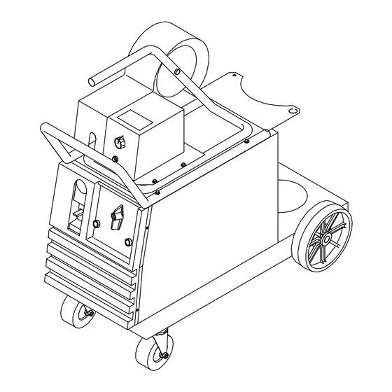
Page 24: Section 7 - Parts List
SECTION 7 – PARTS LIST ST-801 363 Figure 7-1. Main Assembly Auto Arc 175 OM-170 823 Page 22... - Page 25 Parts For Auto Arc 175 Power Source NOTE: All items indented by a dot(s) are included with the item listed directly above. Item Part Item Part Item Part Description Description Description 173 080 Handle 150 783 · Fan Blade 047 721...
- Page 26 ST-801 045 Figure 7-3. Main Assembly Auto Arc 175 Feeder OM-170 823 Page 24...
- Page 27 Parts For Auto Arc 175 Feeder NOTE: All items indented by a dot(s) are included with the item listed directly above. Item Part Item Part Item Part Description Description Description 126 838 Drive Assembly 129 893 Insulator Control Box w/cmpts 092 237 ·...
- Page 28 Notes...
- Page 29 Notes...
-
Page 30: Warranty
Warranty Effective January 1, 2000 (Equipment with a serial number preface of “LA” or newer) This limited warranty supersedes all previous manufacturers Limited Warranty shall not apply to: warranties and is exclusive with no other guarantees or warranties expressed or implied. Consumable components;... -
Page 32: Options And Accessories
OPTIONS AND ACCESSORIES UNIVERSAL CARRYING CART RUNNING GEAR/CYLINDER FLOW GAUGE AND HOSE KIT AND CYLINDER RACK RACK (#043 127) (#042 934) (#042 454) Flow gauge and 5 ft. (1.5 m) gas This cart adds convenience to the Designed for gas cylinder no larger hose for use with CO /Argon Millermatic package.
Need help?
Do you have a question about the 175 and is the answer not in the manual?
Questions and answers