Table of Contents
Advertisement
Quick Links
Read and follow these instructions and all
safety blocks carefully.
Have only trained and qualified persons
install, operate, or service this unit.
Call your distributor if you do not understand
the directions.
auto_arc 7/93 − ST-149 628-B
®
OWNER'S
MANUAL
Auto Arc® 140
CV/DC Welding Power Source/Wire Feeder
For GMAW And FCAW Welding
120 Amperes, 21 Volts At 30% Duty Cycle
Uses 230 Volts AC, Single-Phase Input Power
Feeds .023 Thru .035 Wire
Overheating, Short-Circuit, And Motor Overload Protection
Includes Gas Valve
June 1996
Form: OM-151 016D
Effective With Serial No. KG171523
Give this manual to the operator.
For help, call your distributor
or: MILLER Electric Mfg. Co., P.O. Box 1079,
Appleton, WI 54912
414-734-9821
PRINTED IN USA
Advertisement
Table of Contents
Troubleshooting

Related Manuals for AUTO ARC 140


Summary of Contents for AUTO ARC 140
- Page 1 Form: OM-151 016D Effective With Serial No. KG171523 ® OWNER’S MANUAL Auto Arc® 140 CV/DC Welding Power Source/Wire Feeder For GMAW And FCAW Welding 120 Amperes, 21 Volts At 30% Duty Cycle Uses 230 Volts AC, Single-Phase Input Power Feeds .023 Thru .035 Wire...
- Page 3 ARC WELDING SAFETY PRECAUTIONS WARNING ARC WELDING can be hazardous. PROTECT YOURSELF AND OTHERS FROM POSSIBLE SERIOUS INJURY OR DEATH. KEEP CHILDREN AWAY. PACEMAKER WEARERS KEEP AWAY UNTIL CONSULTING YOUR DOCTOR. In welding, as in most jobs, exposure to certain hazards occurs. Welding is safe when precautions are taken. The safety information given below is only a summary of the more complete safety information that will be found in the Safety Standards listed on the next page.
- Page 4 WELDING can cause fire or explosion. 6. Be aware that welding on a ceiling, floor, bulkhead, or partition can cause fire on the hidden side. Welding on closed containers, such as tanks, drums, or pipes, can cause them to blow up. Sparks can fly off 7.
- Page 5 CONSIGNES DE SÉCURITÉ POUR LE SOUDAGE À L’ARC MISE EN GARDE LE SOUDAGE À L’ARC peut être dangereux. SE PROTÉGER ET PROTÉGER LES AUTRES CONTRE LES BLESSURES GRAVES VOIRE MORTELLES. TENIR LES ENFANTS À L’ÉCART. LES PERSONNES QUI PORTENT UN STIMULATEUR CARDIAQUE NE DOIVENT PAS NON PLUS S’APPROCHER DU POSTE DE SOUDAGE, À MOINS D’AVOIR CONSULTÉ...
- Page 6 LE SOUDAGE peut causer un incendie ou une 5. Prendre garde aux incendies et toujours avoir un extincteur à explosion. proximité. 6. Se rappeler que si l’on soude sur un plafond, un plancher, une cloison Ne pas souder sur des récipients fermés comme des ou autre, le feu peut prendre de l’autre côté.
-
Page 7: Table Of Contents
EMF INFORMATION NOTE Considerations About Welding And The Effects Of Low Frequency Electric And Magnetic Fields The following is a quotation from the General Conclusions Section of To reduce magnetic fields in the workplace, use the following procedures: the U.S. Congress, Office of Technology Assessment, Biological Effects of Power Frequency Electric &... -
Page 9: Section 1 − Safety Information
SECTION 1 − SAFETY INFORMATION mod1.1 2/93 Read all safety messages throughout this manual. Obey all safety messages to avoid injury. Learn the meaning of WARNING and CAUTION. Safety Alert Symbol Signal Word WARNING means possible death or serious injury can happen. WARNING CAUTION CAUTION means possible minor... -
Page 10: Volt-Ampere Curves
2-1. Volt-Ampere Curves The volt-ampere curves show the minimum and maximum voltage and amperage output capabilities of the welding power source. Curves of other settings fall between the curves shown. ssb1.1 10/91 / SB-124 625 Figure 2-1. Volt-Ampere Curves 2-2. Duty Cycle CAUTION EXCEEDING DUTY CYCLE RATINGS will damage unit. -
Page 11: Installing Work Clamp
NOTE Customer must obtain proper welding wire and shielding gas for desired application. 3-1. Installing Work Clamp Insulator Bolt Smaller Hole Work Clamp Tabs Bend tabs around work cable. Work Cable From Unit Tools Needed: 3/8, 7/16 in Ref. ST-025 190-C Figure 3-1. -
Page 12: Gun Polarity For Wire Type
B. Installing Regulator/Flowmeter Obtain gas cylinder and chain to running gear, wall, or other station- ary support so cylinder cannot fall and break off valve. Cylinder Valve Remove cap, stand to side of valve, and open valve slightly. Gas flow blows dust and dirt from valve. -
Page 13: Selecting A Location And Connecting Input Power
3-4. Selecting A Location And Connecting Input Power WARNING ELECTRIC SHOCK can kill. B L O C K E D A I R F L O W c a u s e s • overheating and possible damage to Do not touch live electrical parts. unit. -
Page 14: Installing Drive Rolls And Welding Gun
3-5. Installing Drive Rolls And Welding Gun Pressure Adjustment Pressure Assembly Drive Roll Washers Securing Screw Install drive roll as shown. Gun Securing Knob Gun End Loosen knob. Insert gun end through opening until it bottoms against drive assembly. Tighten knob. -
Page 15: Installing Wire Spool
3-6. Installing Wire Spool WARNING ELECTRIC SHOCK can kill. • Do not touch live electrical parts. • Turn Off welding power source, and disconnect input power before inspecting or installing. swarn1.1 2/93 NOTE If hub tension is too tight, motor fuse F1 can open (see Section 5-2). If hub tension is too loose, wire unravels and can become tangled inside unit. - Page 16 Wire Spool Welding Wire Inlet Wire Guide Pressure Adjustment Knob Drive Roll Outlet Wire Guide Gun Conduit Cable Lay gun cable out straight. Tools Needed: Hold wire tightly to keep it from unraveling. 4 in 6 in (102 mm) (150 mm) Open pressure assembly.
-
Page 17: Section 4 − Operation
SECTION 4 − OPERATION WARNING ELECTRIC SHOCK can kill. ARC RAYS can burn eyes and skin; • NOISE can damage hearing. Always wear dry insulating gloves. • • Wear welding helmet with correct shade of filter. Insulate yourself from work and ground. •... - Page 18 CAUTION ARCING can damage switch. • Do not change Thickness/Voltage switch position while welding. Arcing inside switch can damage contacts, causing switch to fail. warn5.1* 2/93 Fine Tuning/Wire Speed Control Use control to select a wire feed speed. Thickness/Voltage switch setting increases, wire speed range also increases.
- Page 19 Install & Put On Turn On Readjust Controls Connect Personal Safety Equipment & Gas Set Controls Sample Weld And Prepare Equipment Equipment (If Applicable) For Production ssb4.1 10/91 Figure 4-5. Sequence Of Operation For Hard And Flux Cored Wires Install & Connect Adjust Hub Adjust Drive Roll Turn On Equipment...
-
Page 20: Section 5 − Maintenance & Troubleshooting
SECTION 5 − MAINTENANCE & TROUBLESHOOTING WARNING ELECTRIC SHOCK can kill. MOVING PARTS can cause injury. • • Do not touch live electrical parts. Keep away from moving parts. • Turn Off welding power source, and disconnect • Keep away from pinch points such as drive rolls. input power before inspecting, maintaining, or servicing. -
Page 21: Cleaning Or Repairing Drive Assembly
C. Motor Fuse F1 CAUTION STATIC ELECTRICITY can damage parts on circuit boards. • Put on grounded wrist strap BEFORE handling boards or parts. fwarn5.1* 9/91 Turn Off and unplug unit. Unlatch door, and remove door/wrapper. Motor Control Board PC1 Fuse F1 (See Parts List For Size) Pull fuse from fuse holder on PC1. -
Page 22: Gun Maintenance
5-4. Gun Maintenance READ SAFETY BLOCKS at start of WARNING Section 5 before proceeding. FLYING METAL CHIPS AND DIRT can cause injury and damage equipment. • Point gun away from people and in a safe direction when blowing out with compressed air. swarn10.1 10/91 Turn Off unit and disconnect input power. -
Page 23: Troubleshooting
5-5. Troubleshooting WARNING ELECTRIC SHOCK can kill. MOVING PARTS can cause injury. • • Do not touch live electrical parts. Keep away from moving parts. • • Turn Off welding power source, and disconnect Keep away from pinch points such as drive rolls. input power before inspecting, maintaining, or servicing. -
Page 24: Section 6 − Electrical Diagram
SECTION 6 − ELECTRICAL DIAGRAM SB-162 243 Figure 6-1. Circuit Diagram For Welding Power Source OM-151 016 Page 16... - Page 25 OM-151 016 Page 17...
-
Page 26: Section 7 − Welding Methods & Troubleshooting
SECTION 7 − WELDING METHODS & TROUBLESHOOTING mod4.1 9/92 WARNING ELECTRIC SHOCK can kill. ARC RAYS can burn eyes and skin; • NOISE can damage hearing. Always wear dry insulating gloves. • • Wear welding helmet with correct shade of filter. Insulate yourself from work and ground. - Page 27 NOTE Weld bead shape depends on gun angle, direction of travel, electrode extension (stickout), travel speed, thickness of base metal, wire feed speed (weld current), and voltage. ° ° Push Perpendicular Drag GUN ANGLES AND WELD BEAD PROFILES Short Normal Long ELECTRODE EXTENSIONS (STICKOUT) Short...
-
Page 28: Welding Troubleshooting
Large Spatter Deposits POOR WELD BEAD Rough, uneven bead Slight Crater During Welding Bad Overlap Poor Penetration S-0053-A Fine Spatter GOOD WELD BEAD Uniform Bead Moderate Crater During Welding Weld a new bead or layer for each 1/8 in (3.2 mm) thickness in metals being welded. - Page 29 Table 7-2. Excessive Spatter Excessive Spatter − scattering of molten metal particles that cool to solid form near weld bead. S-0636 Possible Causes Corrective Actions Wire feed speed too high. Select lower wire feed speed. Voltage too high. Select lower voltage range. Electrode extension (stickout) too long.
- Page 30 Table 7-5. Excessive Penetration Excessive Penetration − weld metal melt- ing through base metal and hanging un- derneath weld. Excessive Penetration Good Penetration S-0639 Possible Causes Corrective Actions Excessive heat input. Select lower voltage range and reduce wire feed speed. Increase travel speed.
- Page 31 NOTES OM-151 016 Page 23...
-
Page 32: Section 8 − Parts List
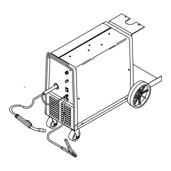
SECTION 8 − PARTS LIST OM-151 016 Page 24... - Page 33 ....149 439 LABEL, Auto Arc MIG welder (both sides of wrapper) ....
- Page 34 Item Dia. Part Mkgs. Description Quantity Figure 8-1. Main Assembly (Continued) ....110 785 TUBE, contact .023 ..........
- Page 35 Item Dia. Part Mkgs. Description Quantity Figure 8-2. Baffle, Center w/Components (Fig 8-1 Item 5) ....058 427 RING, retaining spool ..........
- Page 36 Item Part Description Quantity Figure 8-3. Drive Assembly, Wire (Fig 8-2 Item 31) ..128 189 SCREW, cap stl hexhd .312-18 x 1.750 ........
- Page 37 Item Part Description Quantity Figure 8-4. MWG-160 Gun (Fig 8-1 Item 38) ... . . 110 793 HANDLE ASSEMBLY ..........
- Page 38 Notes...
- Page 39 Notes...
Need help?
Do you have a question about the 140 and is the answer not in the manual?
Questions and answers