
Related Manuals for S&P DUOVENT COMPACT DV


Summary of Contents for S&P DUOVENT COMPACT DV
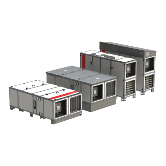
- Page 1 INSTRUCTION MANUAL DUOVENT ® COMPACT DV Ventilation unit with heat recovery www.solerpalau.co.uk...
-
Page 2: Table Of Contents
recovery Ventilation unit with heat ® DUOVENT COMPACT DV Contents General ..........................Introduction ......................... Warranty........................Safety regulations......................General..........................Technical data........................Manufacturing label....................Basic dimensions......................General technical data....................Operation conditions....................Declaration of conformity.................... Transport, storage, acceptance..................Installation........................Place of installation..................... 5.1.1 Distances from building structures (service space)......... -
Page 3: General
Ventilation unit with heat recovery ® DUOVENT COMPACT DV 1. GENERAL 1.1 INTRODUCTION ® This manual is intended for ventilation units with heat recuperation DUOVENT COMPACT DV. Its purpose is to provide as much information as possible for the safe installation, commissioning and use of this equipment. Due to the fact that our products are constantly evolving, we reserve the right to change this manual without prior notice. -
Page 4: Safety Regulations
Ventilation unit with heat recovery ® DUOVENT COMPACT DV 1.3 SAFETY REGULATIONS Adherence to these instructions should not pose any safety, health or environmental risks in accordance with EC directives (CE marked). The same applies to other products used in the device or during installation. Consider the following warnings: –... - Page 5 Ventilation unit with heat recovery ® DUOVENT COMPACT DV 5 - Accessories KL - inlet and outlet damper with preparation for mounting the actuator (if the unit is equipped with the I&C system, the actuator is included) C -mixing flap enabling 100% air circulation with preparation for mounting the actuator filtering class at the fresh air inlet / exhaust from vented area (G4–F9) From 1.1.2016, inlet at least F7, outlet at least M5.
- Page 6 Ventilation unit with heat recovery ® DUOVENT COMPACT DV NOTICE ON CONNECTION OF FAN MOTOR PROTECTIONS WARNING OF THE NECESSITY OF INSULATION OF THE ANTIFREEZE PROTECTION CONTACT SENSOR WARNING - DO NOT OPERATE THE UNIT WHILE CONSTRUCTION WORK IN PROGRESS AIR FLOW CALCULATION PLATE LOCATED AT FAN SUCTION PRESSURE ORIFICE PORT WARNING LABELS...
-
Page 7: Basic Dimensions
Ventilation unit with heat recovery ® DUOVENT COMPACT DV ® 3.2 BASIC DIMENSIONS OF DUOVENT COMPACT DV UNITS COMPACT DV 500 to 1200, vertical arrangement (positions „xV“, AV unit position drawn) ® DUOVENT A+40 Exchanger outlets Condensate drains Ø D Type [mm] [mm]... - Page 8 Ventilation unit with heat recovery ® DUOVENT COMPACT DV COMPACT DV 500 to 1200, floor arrangement (positions „xP“, AP unit position drawn) ® DUOVENT Condensate drains Exchanger outlets Ø D Type [mm] [mm] [mm] [mm] [mm] [mm] [mm] [mm] [mm] [mm] ®...
- Page 9 Ventilation unit with heat recovery ® DUOVENT COMPACT DV COMPACT DV 1800 to 7800, under-ceiling arrangement (positions „xH“, AH unit position drawn) ® DUOVENT UNIT BOTTOM VIEW: UNIT TOP VIEW (FLOOR PLAN): Exchanger outlets Discharge of condensate Ceiling hinges D+20 DETAIL OF CONNECTING FLANGE INTEGRATED IN WALL...
-
Page 10: General Technical Data
Ventilation unit with heat recovery ® DUOVENT COMPACT DV 3.3 GENERAL TECHNICAL DATA ® Detailed technical data of the specific design of the DUOVENT unit are part of the technical specification of the unit, which is shipped together with the unit. The technical specification is located in the packaging on the inside or outside of the service door of the unit. -
Page 11: Operation Conditions
Ventilation unit with heat recovery ® DUOVENT COMPACT DV 3.4 OPERATION CONDITIONS The unit can be used in rooms normal according to IEC 60364-5-51, resp. ČSN 332000-5-51 ed. 3, ČSN 332000-1 ed.2. The ambient temperature must be between -20 and +40 °C. The unit can transport air without solid, fibrous, sticky, aggressive chemical and explosive additives. -
Page 12: Installation
Ventilation unit with heat recovery ® DUOVENT COMPACT DV 5. INSTALLATION The unit can only be installed by a professional installation company authorized in accordance with the Trade Licensing Act. 5.1 PLACE OF INSTALLATION The unit can only be installed in accordance with the "Environmental Protocol", in which the characteristics of all devices that can be placed in this space are clearly defined, and it is not possible to place devices that would affect these conditions in any way. -
Page 13: Distances From Building Structures (Service Space)
Ventilation unit with heat recovery ® DUOVENT COMPACT DV 5.1.1 DISTANCES FROM BUILDING STRUCTURES (SERVICE SPACE) Observe the minimum recommended distances from all obstacles to ensure easy maintenance and operation of the unit. If the unit is fitted with ® Digireg regulation system, it is necessary to ensure free space from the system distribution box of at least 800 mm and the space for free opening of the doors. -
Page 14: Installation Procedure And Connection To Hvac Distribution Lines
Ventilation unit with heat recovery ® DUOVENT COMPACT DV Unit under-ceiling variant of size DV 1800–7800, 8 hinging points (4 at each side). This hinging point can be omitted for DV 1800 and 3000; hinging to this hinge protects the Digireg box, which is turned by 90°... - Page 15 Ventilation unit with heat recovery ® DUOVENT COMPACT DV The unit must be connected to the piping via flexible sleeves to prevent the transmission of vibrations to the air distribution systems. The flexible sleeves must be bridged by a flexible conductive connection for the discharge of static electricity from the device. If the elastic cuffs are secured with spacers against damage during transport and storage, these can be removed only after the attachment of both flanges, on the one hand to the unit and on the other to the air distribution systems.
- Page 16 Neck variants – horizontal arrangement (viewed from upper non-operation side of the unit, floor plan) INLET INLET INLET INLET OUTLET OUTLET OUTLET OUTLET INLET INLET INLET INLET OUTLET OUTLET OUTLET OUTLET INLET INLET INLET INLET OUTLET OUTLET OUTLET OUTLET INLET INLET INLET INLET...
- Page 17 Ventilation unit with heat recovery ® DUOVENT COMPACT DV Neck variants – floor horizontal arrangement (viewed from upper operation side of the unit) INLET INLET INLET INLET OUTLET OUTLET OUTLET OUTLET INLET INLET INLET INLET OUTLET OUTLET OUTLET OUTLET INLET INLET INLET INLET...
-
Page 18: Connection Of Electric Heater
® Installation examples of DUOVENT COMPACT DV units ® ® ® DUOVENT COMPACT DV 500 to 1200 DUOVENT COMPACT DV 500 to 1200 DUOVENT COMPACT DV 500 to 1200 – under-ceiling variant – floor variant – vertical variant ® ® ®... -
Page 19: Connection Of Water Heater
Ventilation unit with heat recovery ® DUOVENT COMPACT DV CAUTION! It is forbidden to remove, bypass or disconnect safety devices, safety functions and protective devices! Any intervention in the internal connection of the heater is forbidden! CAUTION! before service works! •... - Page 20 For correct connection, the direction of water flow is indicated on the housing of the unit by auxiliary labels. heating water inlet heating water outlet air flow air flow heating direction direction water inlet heating water outlet counter-current exchanger connection For the water heater to function properly, it is necessary to bleed the heater after connecting and filling the system with heating water.
-
Page 21: Connection Of Water Cooler
Ventilation unit with heat recovery ® DUOVENT COMPACT DV Units taken out of service must be protected against freezing by draining water from all parts of the unit. Residual water from the exchanger can be expelled with compressed air. When starting the unit at an outdoor air temperature below +5 ° C, the active fluid supply to the heater must be opened before starting the fan, which must have the projected temperature at the heating water supply to the heater. -
Page 22: Connection Of Direct Evaporator
Hydrogen exponent of heating water: pH 7-9 Heating water hardness: 1,0 mval / l The water cooler section is equipped with a drip eliminator, which must always be installed in the unit during cooler operation. All piping must be installed independently of the heat exchangers - the cooling water piping must not act on the necks of the heat exchangers due to its weight and expansion. -
Page 23: Bypass And Mixing Flap
Ventilation unit with heat recovery ® DUOVENT COMPACT DV Vacuum type siphon scheme (SF-P 300): - p (Pa) bottom edge of the condensate tray unit check valve - ball p bar (Pa) floor level The vacuum siphon (SF-P300) contains a ball that serves as a non-return valve for the proper function of the water-free siphon and prevents odours from entering the unit. - Page 24 ® Location of mixing and bypass damper for DUOVENT 1800 to 7800 units: Bypass flap (BP) ETA flap Mixing flap (MX or C) ODA flap 500, 800, 1200 units – with „C“ circulation mode: ® Location of mixing and bypass flap for DUOVENT Bypass flap (BP) Circulation flap (C)- part 2 (enables circulation mode)
-
Page 25: Inlet And Outlet Flap
Ventilation unit with heat recovery ® DUOVENT COMPACT DV Control torques and types of bypass and mixing flap actuators: min. control unit type possible types of BELIMO actuators torque [Nm] ® DUOVENT 500, 800, 1200 CM24-SR-L or R / CM24-L or R / CM230-L or R ®... -
Page 26: Regulation Unit For Esu Water Heater Or Esuch Water Cooler
5.2.10.2 ESU WATER HEATER OR ESUCH WATER COOLER CONTROL UNIT The ESU or ESUCH unit must be ordered as a separate item because they are not included with the unit. CAUTION! The design of a suitable mixing unit must be individually adapted to the conditions of the application in order to ensure sufficient valve authority! -
Page 27: Electrical Installation
Ventilation unit with heat recovery ® DUOVENT COMPACT DV 6. ELECTRICAL INSTALLATION In general, it is necessary to observe the provisions of ČSN 12 2002 and other related regulations. The device must be disconnected from the mains during any inspection or service activities. The connection and earthing of electrical equipment must comply in particular with ČSN 33 2000-5-51 ed.3, ČSN 33 2000-5-54 ed.3 and the ČÚBP and ČBÚ... -
Page 28: Digital Regulation System Digireg
6.3 INSTRUMENTATION AND CONTROL (I&C) SYSTEM ® The standard part of the unit is its own control system. The design of the unit is ready for cooperation with the Digireg digital controller. ® 6.3.1 DIGITAL REGULATION SYSTEM DIGIREG The control system is located in a compact sheet steel switchboard equipped with a main switch, digital controller on the PCB board and safety and switching elements for individual HVAC units. -
Page 29: Technology Scheme Of Digireg I&C Systems
Ventilation unit with heat recovery ® DUOVENT COMPACT DV The actual commissioning and setting of the basic parameters of the controller must be performed by an authorized company with authorization Ltd. and training from S&P UK Ventilation Systems The cables must be secured outside the unit against being pulled out in the installed bushings. The cable routes of safe and mains voltage must be separated due to electromagnetic compatibility requirements. -
Page 30: Instrumentation And Control System
6.3.5 CONTROL The controller is operated exclusively via the touch control. Service settings are performed by the appropriate service program, which is only available to trained and certified companies. ® Touch control CP for Digireg 7. COMMISSIONING The device may only be put into operation for the first time by a suitably qualified specialist. 7.1 INSTALLATION AND CONNECTION CHECK Before the first commissioning, it is necessary to check: –... -
Page 31: Operation And Maintenance
Ventilation unit with heat recovery ® DUOVENT COMPACT DV 8. OPERATION AND MAINTENANCE These instructions serve as an aid for professionals, operators of air handling units, or investors who are assumed to already have experience with the operation of air conditioning systems. The instructions are especially important for the start-up period of the entire system, when more detailed operating regulations are not available. -
Page 32: Replacement And Maintenance Of Filter
Table of dimensions of filter inserts for DV 500-1200: ETA filter size ETA (mm) ODA filter size ETA (mm) Size of Neck position – VERTICAL B1 (mm) B2 (mm) B1 (mm) B2 (mm) DUOVENT DV all positions AV, BV, EV, FV, AV2, BV2, FV2, EV2 CV, DV, GV, HV, CV2, DV2, HV2, GV2 IV, JV, MV, NV, JV2, IV2, NV2, MV2 KV, LV, OV, PV, LV2, KV2, PV2, OV2... -
Page 33: Fan Maintenance
Ventilation unit with heat recovery ® DUOVENT COMPACT DV Filter replacement procedure (vertical variant) - slide the filter out of the rails after opening the door: Filter replacement procedure (horizontal variant) - slide the filter out of the rails after opening the door, resp. roof in roof variant: 8.2.2 FAN MAINTENANCE The fans are protected by filters and can therefore only be slightly soiled. -
Page 34: Periodic Inspections
8.2.4 PERIODIC INSPECTIONS Perform periodic inspections at least once a year as part of a summer service inspection. It is optimal to carry out inspections twice a year, usually before and after the end of the winter season. During the regular service inspection it is necessary in particular: –... -
Page 35: Warranty
24 (TWENTY-FOUR) MONTH PRODUCT WARRANTY S&P UK Ventilation Systems Limited warrants that the DUOVENT COMPACT DV will be free from defective materials and workmanship for the period of 24 (twenty-four) months from the date of original purchase. In the event that we find any part is defective the product will be repaired or at the company's discretion, replaced without charge provided that the product has been installed in accordance with the enclosed instructions and all applicable standards and national and local building standards.
Need help?
Do you have a question about the DUOVENT COMPACT DV and is the answer not in the manual?
Questions and answers