
Subscribe to Our Youtube Channel
Related Manuals for Carbatec JN-BX200P


Summary of Contents for Carbatec JN-BX200P
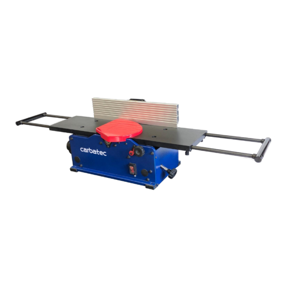
- Page 1 WARRANTY OWNERS MANUAL 200mm Professional Benchtop Segmented / Spiral Head Jointer JN-BX200P...
-
Page 2: General Safety
GENERAL SAFETY NOTE: The [WARNING!] and [CAUTION!] symbols indicate a potentially hazardous situation which, if not avoided, COULD result in death or serious injury. READ THIS MANUAL completely before assembling and operating this machine. [WARNING!] TO AVOID serious injury, death, or damage to the machine, please read, understand, and follow, all Safety and Operating Instructions before assembling and operating this machine. - Page 3 appropriate for the dust exposure, and wash exposed areas with soap and water. [WARNING!] ALWAYS wear eye protection. Any machine can throw debris into the eyes during operations, which could cause severe and permanent eye damage. Everyday eyeglasses are NOT safety glasses. ALWAYS wear Safety Goggles (that comply with applicable Australian Standards/New Zealand Standards, referred to as AS/NZS) when operating power tools.
- Page 4 [WARNING!] DO NOT operate any machine or tool if under the influence of drugs, alcohol, or medication. Prior to operation EACH AND EVERY time, check for damaged parts prior to using any machine. Carefully check all guards to see that they operate properly, are not damaged, and perform their intended functions.
- Page 5 THE USE of long extension cords is not recommended for 230V equipment. It is better to arrange the placement of your equipment and the installed wiring to eliminate the need for an extension cord. If an extension cord is necessary, seek qualified advice to determine the minimum gauge for the extension cord based on the length being used.
- Page 6 9. USE only parts or accessories as described in this manual and recommended by Carbatec. 10. DO NOT pull the machine by the power cord. NEVER allow the power cord to come in contact with sharp edges, hot surfaces, oil or grease.
-
Page 7: Specific Safety Instructions
15. This machine is designed for the processing of wood only. DO NOT use with other materials. 16. [WARNING!] NEVER position fingers, thumbs or any part of your body, near the cutterhead or blade. 17. Long pieces of stock should ALWAYS be supported with some type of fixture. -
Page 8: Unpacking & Inventory
UNPACKING & INVENTORY Check shipping carton and machine for damage before unpacking. Carefully remove packaging materials, parts and machine from shipping carton. Always check for and remove protective shipping materials around motors and moving parts. Lay out all parts on a clean work surface. Remove any protective materials and coatings from all of the parts and the jointer. -
Page 9: Power Source
ASSEMBLY WARNING! MAKE CERTAIN THAT THE MACHINE IS DISCONNECTED FROM THE POWER SOURCE. FENCE ASSEMBLY PROCEDURE 1. Assemble the fence bracket (A) to the jointer base (B). Remove the four Soc Button Head Screws (C) on the rear frame to lock the bracket in place. SEE FIG. 1 2. - Page 10 ASSEMBLY (cont.) 3. Adjust the fence sliding bracket (A) to the middle of the fence (B), referring to the center of fence cut-out (C) use two M6x16mm soc button head screws (D) to lock the sliding bracket in position. SEE FIG. 3 4.
- Page 11 ASSEMBLY (cont.) 5. With the tilt lock lever assembly in between the mounting and sliding bracket, put on special nut (A), and turn the lever to lock both brackets into position. SEE FIG. 5 6. Use an angle gauge (A) to measure the 90° & 135° between the Fence and Jointer Table Top. Adjusting can be done by loosening or tightening the Nylok Hex Soc Head Screw (B).
-
Page 12: Cutterhead Guard
ASSEMBLY (cont.) CUTTERHEAD GUARD The cutterhead guard has a tension return spring. The tension on this spring is set at the factory. When the guard is installed properly it should return to the fence automatically after the work piece has passed over the cutterhead. Be sure the guard is functioning properly every time before using the jointer. -
Page 13: Switch Assembly
ASSEMBLY (cont.) LOCK KNOB ASSEMBLY Attach knob (A) to the jointer by tightening the hex nut (B) by 10 mm, 13mm open end wrench (C). SEE FIG. 10 & 11 SWITCH ASSEMBLY The jointer is turned on by flipping the switch into the up position and it is turned off by flipping the The machine is fitted with a No Volt Release (NVR) safety switch. -
Page 14: Fence Adjustments
ADJUSTMENTS WARNING! MAKE CERTAIN THAT THE MACHINE IS DISCONNECTED FROM THE POWER SOURCE BEFORE ANY ADJUSTMENTS ARE MADE. FENCE ADJUSTMENTS 1. To move the fence across the table by loosening lock lever (A), slide the fence to the desired position on the table and tighten lock lever (A). SEE FIG 13. FIG 13 NOTE: Lock lever (A) and (B) can be repositioned by pulling up the lever and repositioning it on the nut located underneath the lever. - Page 15 ADJUSTMENTS (cont.) 5. Tighten set screw (D) by hex wrench until it contacts stop (E) SEE FIG 16. FIG 16 . Put a square (C) on the table with one end against the fence to adjust the fence until it is exactly 135 degrees to the table.
- Page 16 ADJUSTMENTS (cont.) WARNING! MAKE CERTAIN THAT THE MACHINE IS DISCONNECTED FROM THE POWER SOURCE BEFORE ANY ADJUSTMENTS ARE MADE. INFEED / OUTFEED TABLE ADJUSTMENT The infeed and outfeed tables are adjustable for coplanar or parallelism if ever necessary. These are set at the factory. If after planing or edge joining a work piece and adjustment is necessary, follow these instructions.
- Page 17 ADJUSTMENTS (cont.) INFEED / OUTFEED EXTENSION SUPPORT ADJUSTMENT The infeed and outfeed extension supports are adjustable for coplanar or parallelism if ever necessary. These are set at the factory. If after planing or edge joining a work piece and adjustment is necessary, follow these instructions. At left of jointer, place a straight edge on the outfeed table across the outfeed extension support and check for parallelism.
- Page 18 OPERATIONS NOTE: This operations section was designed to give instructions on the basic operations of this jointer. However, it is in no way comprehensive of every jointer operation. It is strongly recommended that you read books, trade magazines, or get formal training to maximize the potential of your jointer while minimizing the risks.
-
Page 19: Direction Of Grain
OPERATIONS (cont.) DIRECTION OF GRAIN Avoid feeding work into the jointer against the grain. The result will be chipped and splintered edges. Feed with the grain to obtain a smooth surface. SEE FIG 19. FIG 19 The jointer can be set to cut any depth from a very thin shaving to 1/8” deep. The pointer on the scale is to indicate the depth of cut. - Page 20 OPERATIONS (cont.) Refer to Table 20A for recommended maximum depth of cut for different board width of soft and hard woods. Table 20A Maximum depth of cut Board Width Soft Wood Hard Wood Less than 6” 1/8” 3/32” 7” 3/32” 5/64”...
-
Page 21: Push Blocks
OPERATIONS (cont.) PUSH BLOCKS CAUTION! A set of push blocks (A) should be used whenever possible to minimize all danger to your hands. SEE FIG 22 FIG 22 WARNING! ALWAYS USE PUSH BLOCKS WHEN PERFORMING SURFACING OPERATIONS AND NEVER PASS YOUR HANDS DIRECTLY OVER THE CUTTERHEAD. JOINTING AN EDGE This is the most common operation for the jointer. -
Page 22: Maintenance
SURFACING / PLANING Surfacing is similar to the edge jointing operation except for the position of the work piece. For surfacing, the major flat surface of the work piece is placed on the infeed table of the jointer with the narrow edge of the work piece against the fence. The work piece is moved from the infeed table, across the cutterhead to the outfeed table, establishing a flat surface on the work piece. - Page 23 MAINTENANCE (cont.) WARNING! MAKE CERTAIN THAT THE MACHINE IS DISCONNECTED FROM THE POWER SOURCE BEFORE PERFORMING ANY MAINTENANCE PROCEDURES BLADE (CUTTER INSERT) REPLACEMENT WARNING: To prevent serious personal injury NEVER rotate the cutterhead by hand. Cutter insert are razor sharp! Always wear heavy leather gloves when handling the cuttherhead.
-
Page 24: Replacing The Belt
MAINTENANCE (cont.) Note: Proper cleaning is critical to achieving a smooth finish. Dirt or dust trapped between the cutter insert and cutterhead will slightly raise the cutter insert and make noticeable marks on your work piece the next time you use the machine. REPLACING THE BELT Use 4MM Allen Key to loosen the screw of belt guard. - Page 25 MAINTENANCE (cont.) Press the belt on the cutterhead pulley. SEE FIG 28. Then rotate cutterhead pulley on clockwise and assemble the belt. SEE FIG 29. FIG 28 FIG 29 Replace the belt guard. SEE FIG 30 and 31. FIG 30 FIG 31...
-
Page 26: Troubleshooting Guide
TROUBLESHOOTING GUIDE Motor and Machine Operation PROBLEM LIKELY CAUSE SOLUTION Motor will not start. Not plugged in. Check the power source. Blown circuit. Replace fuse, reset breaker, or call Lockout key removed. electrician. Improper Voltage. Replace lockout key. Fuses or circuit Short circuit in line cord or plug. - Page 27 TROUBLESHOOTING GUIDE (cont.) PROBLEM LIKELY CAUSE SOLUTION Vibration when Loose or damaged cutter insert. Tighten or replace cutter insert. operating jointer Damaged belt. Replace belt Worn cutterhead bearing. Check/replace cutterhead bearing. Infeed table hard to Table lock is engaged or Completely loosen the table lock.
- Page 30 Ser# Drawing Description Spec 40180H-001 TABLE 40180H-002 RIGHT COVER 40180H-003 OUTFEED SUPPORT SET SCREW M6xP1.0x8L 40180H-005 LEFT COVER BUTTON HD SCREW M6xP1.0x12L SELF TAP SCREW 1/4”x19L 40180H-008 DUST CHUTE FOAM SEAL 40180H-010 FOAM SEAL SPL 3002 FRONT FRAME 40180H-013 DUST PORT SPL 3017 BEARING RETAINER BEARING...
- Page 31 Ser# Drawing Description Spec BUTTON HD SCREW M5xP0.8x10L FLANGE NUT M6xP1.0 40180H-049 TIE ROD SPL 3018 CORD CLAMP SPL 3004 INFEED SUPPORT KNOB 40180H-053 BUSHING SET SCREW SPL 3005 BRACKET SPL 3056 SET SCREW M6x16L HEX NUT M6xP1.0 SPL 3007 ADJUSTING ROD SPL 3008 SHAFT...
- Page 32 Ser# Drawing Description Spec 133S TILT LOCK LEVER ASSY 135S TILT LOCK LEVER ASSY SPL 3040 FENCE SLIDE BRACKET SPL 3039 FENCE BRACKET FLAT WASHER M6*Ø12.5*2.0t SOC BUTTON HD SCREW M6x16L 300S MOTOR 1345913 MOTOR COVER SCREW M5*P0.8*8L SCREW M5*P0.8*20L ø...
- Page 34 2 years from date of sale. Carbatec Pty Ltd ABN 84 010 706 242 info@carbatec.com.au | Phone 1800 658 111 | www.carbatec.com.au...
- Page 35 Carbatec Pty Ltd ABN 84 010 706 242 info@carbatec.com.au Phone: 1800 658 111 128 Ingleston Road, Wakerley Queensland Australia 4154 www.carbatec.com.au...
Need help?
Do you have a question about the JN-BX200P and is the answer not in the manual?
Questions and answers