Table of Contents
Advertisement
Quick Links
Advertisement
Table of Contents

Related Manuals for Multiplex WELBILT Blend-In-Cup MB-8-1PP6


Summary of Contents for Multiplex WELBILT Blend-In-Cup MB-8-1PP6
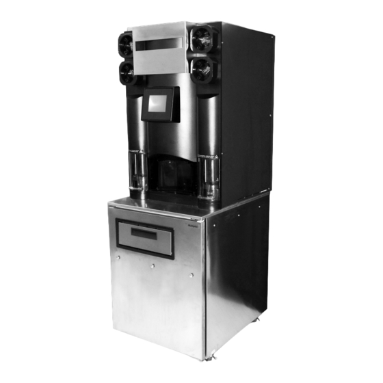
- Page 1 Blend-In-Cup® (BIC) 600 lb R290 Ice on Board Beverage System Installation, Operation and Maintenance Manual Original Instructions — This manual is updated as new information and models are released. Visit www.welbilt.com for the latest manual. Part Number 9294844 April 5, 2023...
- Page 2 Safety Notices Caution As you work on this equipment, be sure to pay close Proper installation, care and maintenance are essential attention to the safety notices in this manual. Disregarding for maximum performance and trouble-free operation the notices may lead to serious injury and/or damage to the of your equipment.
- Page 3 Warning DANGER - RISK OF FIRE OR EXPLOSION All covers and access panels must be in place and Flammable refrigerant used. Risk of Fire or Explosion properly secured before operating this equipment. due to Flammable Refrigerant Used. Follow Handling Instructions Carefully in Compliance With U.S. and Warning Canadian Government Regulations.
- Page 4 Caution Do not obstruct machine vents or openings. Caution Do not connect or insert unapproved devices into the USB port on unit. USB port is for software updates only, it is NOT for charging external devices.. Caution- Risk of Damage to Blender Do NOT operate the blender in dry conditions.
-
Page 5: Table Of Contents
Table of Contents Section 1 General Information Read This Manual ....................... 7 About Blend-In-Cup ......................7 Unit Inspection ........................7 Model Numbers ........................7 Serial Number Location ..................... 7 Warranty Information ......................8 Specifications ........................9 Dimensions ...............................9 Capacity & Weight ..........................9 Product Delivery Location ........................ - Page 6 Table of Contents (continued) Section 4 Maintenance General Maintenance .......................37 Door Gasket Maintenance ....................... 37 Drain Maintenance - Inside Lower Cabinet ................37 Refrigerators ............................38 Stainless Steel Care & Cleaning ...................... 38 Doors/Hinges ............................38 Preventing Blower Coil Corrosion ....................38 Daily Cleaning - Zone 1 ....................39 Gather the Following Supplies .......................
-
Page 7: General Information
Section 1 General Information Read This Manual Warning Multiplex developed this manual as a reference guide Do not damage the refrigeration circuit when installing, for the owner/operator and installer of this equipment. maintaining or servicing the unit. Please read this manual before installation or operation of the machine. -
Page 8: Warranty Information
If a warranty card is not returned, the warranty period can begin when the equipment leaves the Multiplex factory. No equipment may be returned to Multiplex without a written Return Materials Authorization (RMA). Equipment returned without an RMA will be refused at the dock and returned to the sender at the sender’s expense. -
Page 9: Specifications
Section 1 General Information Specifications DIMENSIONS Plan View Elevation View Side View 26.00" (66 cm) 71.19" (181 cm) 60.25" (153 cm) 32.82" (83 cm) 36.15" (92 cm) 32.82" (83 cm) 65.19" (166 cm) 26.00" (66 cm) 75.07" (191 cm) 39.09" (99 cm) Warning To avoid instability the installation area must be capable of supporting the weight of the equipment and a full... -
Page 10: Product Delivery Location
General Information Section 1 PRODUCT DELIVERY LOCATION REFRIGERANT CHARGE The location selected for the Blend-In-Cup Beverage System Important must meet the following criteria. Due to continuous improvements, this information is • The air temperature must be at least 40°F (4°C), but for reference only. -
Page 11: Electrical
Section 1 General Information ELECTRICAL Warning All wiring must conform to local, state and national codes. Minimum Circuit Ampacity Grounding Instructions The minimum circuit ampacity is used to help select the Warning wire size of the electrical supply. (Minimum circuit ampacity The machine must be grounded in accordance with is not the Blend-In-Cup Beverage System’s running amp national and local electrical codes. -
Page 12: Air / Co , Plain & Chilled Water
General Information Section 1 Air / CO , Plain & Chilled Water • Use supplied 3/8” (.95 cm) panel-mounted hose barb Warning and 6’ (1.8 m) of beverage tubing to connect labeled Connect to a potable water supply only. coupling body fitting(s) on back of unit for each supply connection. -
Page 13: Regulator Settings & Location
Section 1 General Information REGULATOR SETTINGS & LOCATION Models MB-8-1PP6 Regulator Settings Important Air/CO2 Chilled Water (Pumps) Regulator Air/CO Requires the pressure measurement to be taken Regulator 35 psi (0.24 MPa, 35 psi (0.24 only when a product pump is being activated (product 241 kPa, 2.41 bar) MPa, 241 kPa, pump during flow conditions). -
Page 14: Drain Connections
General Information Section 1 DRAIN CONNECTIONS Models MB-8-1PP6 Drain • Connect supplied 1” ID hose to hose-barb connection on machine. • Drain lines must have a 1.5 inch drop per 5 feet of run (2.5 cm per meter), and must not create traps. •... -
Page 15: Installation
Keep product bags in a cooler at least 24 hours These instructions are provided to assist the qualified prior to installation. installer. Contact your Multiplex for information regarding start-up services. Any damage should be noted and reported to the delivering carrier immediately. -
Page 16: Connections
Installation Section 2 CONNECTIONS Electrical See “System Pressures” on page 12 and “Regulator Settings & Location” on page 13 See “Electrical” on page 11 1. Confirm correct orientation of Water and Air/CO 5. If all electrical and grounding requirements have been fittings. -
Page 17: Start-Up & Cleaning
Section 2 Installation START-UP & CLEANING Checklist Tune-Up Reminder Review before proceeding to Start-Up & Cleaning. 9. The Tune-Up reminder screen will appear during initial installation, press the green check to continue. Has all of the internal packing been removed? Have all of the electrical, water and CO connections been made? Is there proper clearance around the machine for... -
Page 18: Calibrate
Installation Section 2 13. Select Zone 2, Clean and sanitize the Blend-In-Cup CALIBRATE machine by following the on screen instructions. See “Calibration Procedure” on page 29 18. Product calibration can be performed once operating temperature has been reached. Once completed, the Blend-In-Cup machine is ready for use. -
Page 19: Operation
Section 3 Operation Component Identification Lid Holders (Optional) Cup Holders Blending Station(s) Touch Screen Product USB Port Dispense Area Power Switch Whip Cream Door (Optional) Syrup Rail & Dividers (Optional) Product Bins Cabinet Door (Can be configured for Right- Pull Out Tray or Left-Hand) NOTE: The Plain Water &... -
Page 20: Ice Making
Operation Section 3 ICE MAKING Ice Machine Switch - Rear of the Unit Ice Machine ON/OFF Switch The ice machine will not start until: 1. The ice machine ON/OFF switch is in the “ON” position. 2. Ice does not contact the bin level sensor/switch. 3. -
Page 21: Touch Screens
Section 3 Operation Touch Screens The “easy ToUCH” screen has four selections. One is for the drink making procedure: Drink Selection displays by default at start-up. The Manager’s Menu is for accessing the machine’s settings. Inventory is for product information and Cleaning is for routine maintenance of the machine. -
Page 22: Flavor Selection Screen
Operation Section 3 FLAVOR SELECTION SCREEN The Flavor Selection screen appears after a Drink Selection has been made. Flavor options will vary depending on what recipes are configured on the unit. This screen’s primary function is to select a drink flavor. Cleaning Nozzle &... -
Page 23: Size Screen
Section 3 Operation SIZE SCREEN The Size screen appears after a drink flavor has been chosen from the Flavor Selection screen. This screen’s primary function is to select size and make a drink. Optional Add-Ins are also performed through this screen if the drink requires them. Cleaning Nozzle &... - Page 24 Operation Section 3 Procedure to Make a Drink NOTE: Ice must be present in the ice hopper, product must be connected and primed to produce a drink. 4. Drink size is the next selection. Warning- Risk of Injury to Persons- Moving Parts Blend chambers contain fast-moving, sharp blender blades.
- Page 25 Section 3 Operation 9. While the drink is mixing, the top of the screen will read BLENDING Drink Status NOTE: On dual mixer units, a second drink can be selected and blended simultaneously. 10. Follow all drink specific screen directions for add-ins if necessary and press the flashing arrow if prompted.
-
Page 26: Main Menu Screen
Operation Section 3 MAIN MENU SCREEN Accessed primarily though the Drink Selection screen, this screen’s primary function is to provide access to all other procedures and adjustments that can be performed on the unit. Drink Recipes Menu Inventory Managers Menu Cleaning Category Icon Descriptions Inventory... -
Page 27: Manager's Menu Screen
Section 3 Operation MANAGER’S MENU SCREEN Accessed though the Main Menu screen, this screen’s primary function is to provide on-screen access to Manager-only functions. Clear Password Password Display Display Area Password Input Keypad Accept Cancel Password How to Access Manager Menu Features After selecting Manager’s Menu icon from the Main Menu, the Password Keypad screen appears. - Page 28 Operation Section 3 Assigning Flavors 6. Select a slot you want to assign a flavor to. 1. From the Main Menu select the Manager icon. 7. Select from available flavors. 2. Type in the password. NOTE: Available flavors will vary depending on the recipe file that is loaded on the machine.
-
Page 29: Calibration Procedure
Section 3 Operation CALIBRATION PROCEDURE Important : : Pre-calibration Checklist 1. From the Main Menu, select the Manager icon. If calibrating ice, go to the Drink Menu and dispense 4 large cups of ice prior to calibrating. Check for empty product bags in the cabinet and replace if necessary. - Page 30 Operation Section 3 6. Follow the on-screen instructions and do the following: 8. The calibration screen will display again with the weight entered on the previous screen. • Get a digital scale. • Tare empty cup weight. A. If the weight displayed is incorrect, press the •...
- Page 31 Section 3 Operation IMPORTANT PRODUCT INVENTORY SCREEN This screen’s primary function is to provide visual product inventory information for the user. The Product Inventory screen is normally accessed through the Main Menu. Product Bin Number Product Inventory Unassigned Bar Graph Product Bin Days Until Expiration...
- Page 32 Operation Section 3 Procedure to Install a Product Bag 1. From the Main Menu touch the Inventory icon. 7. Press the Green Check to continue. 8. Select inventory level from FULL BAG or NO BAG. 2. On the Inventory screen, select the product to be installed.
-
Page 33: Cleaning Screen
Section 3 Operation CLEANING SCREEN The Cleaning screen appears after selected from the Main Menu or when prompted to perform routine cleaning. This screen’s primary function is to perform routine cleaning and sanitation of the machine. Cleaning Countdown ZONE 1 ZONE 3 Daily Cleaning Monthly Cleaning... -
Page 34: Other Operations
Testing in the machine with the product will be necessary. Position 1 Position 2 Contact the Multiplex team for a detailed cup evaluation. • Cup heights between 4.25" and 7.00". • Cup opening diameter greater than 3.50" and less than 4.18". -
Page 35: Maintenance
Section 4 Maintenance General Maintenance This section covers common unit components and their care. the Ice Machine is supplied with hard water, more frequent cleaning should be performed. If the condenser air filter is The chart below is an overview of the maintenance that totally blocked after one week, more frequent cleaning is the end user and service technician should perform, and recommended. -
Page 36: Refrigerators
Maintenance Section 4 REFRIGERATORS Caution Warning Never use an acid-based cleaning solution! Many food products have an acidic content, which can deteriorate Do not damage the refrigeration circuit when installing, the finish. Be sure to clean the stainless steel surfaces of maintaining or servicing the unit. -
Page 37: Daily Cleaning - Zone 1
Section 4 Maintenance Daily Cleaning - Zone 1 GATHER THE FOLLOWING SUPPLIES NOTE: The following procedures are the basic daily cleaning instructions, on-screen instructions can vary depending Follow the on-screen instructions and gather the following on the recipe that was created with the MenuConnect supplies: program. -
Page 38: Blenders / Dispense Area Cleaning & Sanitizing
Maintenance Section 4 BLENDERS / DISPENSE AREA CLEANING & SANITIZING Grate Removal / Blender Station Wash Blender Door Removal Warning 1. Slightly open blender door. 2. Squeeze at bottom of door. The blender station contains sharp moving parts. Wear gloves to protect hands. 3. - Page 39 Section 4 Maintenance Wash Blender Grate(s) / Door(s) Blender Wash 1. Take all grates, cup cover seals, and doors to sink to wash Warning- Risk of Injury to Persons- Moving Parts and sanitize. Do not put in dishwasher or power soaker. Blend chambers contain fast-moving, sharp blender blades.
- Page 40 Maintenance Section 4 Blender Sanitizing Blender Station Sanitizing Warning Warning- Risk of Injury to Persons- Moving Parts The blender station contains sharp moving parts. Wear Blend chambers contain fast-moving, sharp blender gloves to protect hands. blades. Never put hands or other body parts into the blend chamber while blender blades are operating.
- Page 41 Section 4 Maintenance Dispense Area Cleaning Caution Do Not Insert a brush or sharp object into the red dispense nozzles. 1. Spray all dispensing area surfaces with cleaning solution, then use approved cleaning brush to thoroughly scrub area. 2. Thoroughly spray each individual dispense nozzle with cleaning solution and apply cleaner to each individual dispensing valve, then use approved towel to wipe the area.
-
Page 42: Weekly Cleaning - Zone 2
Maintenance Section 4 Weekly Cleaning - Zone 2 GATHER THE FOLLOWING SUPPLIES NOTE: The following procedures are the basic weekly cleaning instructions, on-screen instructions can vary Follow the on-screen instructions and gather the following depending on the recipe that was created with the supplies: MenuConnect program or options chosen in the Managers Clean towels (Cloths*) -
Page 43: Product Line Cleaning & Sanitizing
Section 4 Maintenance PRODUCT LINE CLEANING & SANITIZING At Back Room Sink Whip Cream Door, Gasket Seals, & Drip Tray* 1. Put on gloves & safety glasses.* 1. Move the product bags, canister, and any tray products to walk-in cooler. 2. - Page 44 Maintenance Section 4 Connect Cleaning Tubes Sanitize Lines 1. Place cleaning manifold into bucket #1 - Cleaner. 1. Remove cleaning manifold from bucket #2 - Warm Rinse Water and place into bucket #3 - Sanitizer. DO NOT 2. Connect 4 shorter tubes to bottom white nozzles - 4 ALLOW CLEANING MANIFOLD TO TOUCH THE FLOOR.
- Page 45 Section 4 Maintenance Purging Lines Reinstall Inventory 1. Disconnect the cleaning hoses from the white nozzles. 1. Retrieve product holders from refrigerated storage and reinstall each into their correct slot number. 2. At each white nozzle remove cleaning manifold tube and spray with sanitizer, then reinstall each cleaning 2.
-
Page 46: Sanitizing Ice Bin (Optional)
Maintenance Section 4 SANITIZING ICE BIN (OPTIONAL) Removal of Ice *These steps will only display during the ZONE 2 Cleaning on units with this feature turned on in the Managers Menu. If this Follow the on screen instructions: feature is not active, the interface will automatically proceed to 1. - Page 47 Section 4 Maintenance Sanitizing Ice Bin Prep Rinsing Sanitizer Prep 1. Install splash guard in dispense area. 1. Put on gloves and safety glasses.* 2. Fill sanitizer bucket with water and add sanitizer. 3. Place cleaning hose into the sanitizer bucket. 1.
- Page 48 Maintenance Section 4 Grate Removal / Blender Station Wash Blender Door Removal Warning 1. Slightly open blender door. 2. Squeeze at bottom of door. The blender station contains sharp moving parts. Wear gloves to protect hands. Follow the on screen instructions: •...
- Page 49 Section 4 Maintenance Clean Blender Shaft Bushing * Reinstall Blender Door(s) NOTE: Some units do not have a blender shaft bushing. 1. Reinstall blender door(s). 1. Follow the blender shaft up above the blender cap, use fingers to pull the bushing out of the blender chamber. •...
- Page 50 Maintenance Section 4 Blender Wash Blender Sanitizing Warning- Risk of Injury to Persons- Moving Parts Warning- Risk of Injury to Persons- Moving Parts Blend chambers contain fast-moving, sharp blender Blend chambers contain fast-moving, sharp blender blades. Never put hands or other body parts into the blades.
- Page 51 Section 4 Maintenance Blender Station Sanitizing Dispensing Area Cleaning Warning Important The blender station contains sharp moving parts. Wear Do Not Insert a brush or sharp object into the red gloves to protect hands. dispense nozzles. 1. Completely spray blender station with cleaning 1.
-
Page 52: Drain Cleaning - Bio-Shield® (Optional)
Maintenance Section 4 DRAIN CLEANING - BIO-SHIELD® (OPTIONAL) Mix Drain Cleaning Solution *Only for units with this feature. These steps will only display during the ZONE 2 Cleaning on units with this feature turned Important on in the loaded recipe file. If this feature is not active, the When in contact with drain cleaning chemicals gloves interface will automatically proceed to “Weekly Cleaning and safety glasses are recommended. - Page 53 Section 4 Maintenance Post Drain Cleaning Weekly Cleaning Completed 1. Open the pressure relief knob again by turning 1. Remove gloves and safety glasses.* counter-clockwise. 2. Weekly cleaning has been completed. 2. Remove cap from the dispenser. 3. Unit will need to be cleaned again in 7 days. 3.
-
Page 54: Monthly Cleaning - Zone 3
Maintenance Section 4 Monthly Cleaning - Zone 3 GATHER THE FOLLOWING SUPPLIES NOTE: All steps will be displayed on screen. *These items are optional and may not be displayed on all easyToUCH screens Follow the on-screen instructions and gather the following during ZONE 3 Cleaning. -
Page 55: Ice Maker Cleaning & Sanitizing
Section 4 Maintenance ICE MAKER CLEANING & SANITIZING Removal of Ice Sanitizing Ice Maker Prep Follow the on screen instructions: 1. Put on gloves and safety glasses.* 1. Install ice removal chute in dispenser area. 2. Install splash guard in dispense area. 2. - Page 56 Maintenance Section 4 Discard Sanitizer & Ice Purge Prep Sanitizing Ice Bin & Water Nozzles Prep 1. Discard remaining sanitizer from the bucket. 1. Put on gloves and safety glasses.* 2. Remove splash guard from the dispense area. 2. Install splash guard in dispense area. 3.
- Page 57 Section 4 Maintenance Rinsing Sanitizer Prep Removal of Ice 1. Install splash guard in the dispense area. 1. Install ice removal chute in dispenser area. 2. Place empty bucket on floor under ice chute. 2. Press the Green Check to begin the plain water rinse cycle. •...
-
Page 58: Other Monthly Tasks
Maintenance Section 4 OTHER MONTHLY TASKS Air Filters Cleaning the Condenser Coil For units equipped with upper and/or lower air filters. Each In order to maintain proper refrigeration performance, the month check the air filters to be sure they are clean and condenser fins must be cleaned of dust, dirt and grease allow proper airflow. -
Page 59: Biannual Descaling - Zone 3
Section 4 Maintenance Biannual Descaling - Zone 3 Descaling is recommended every six (6) months. More frequent descaling may be required in some existing water conditions. Follow carefully any instructions provided with the bottles of Ice Machine Descaling or sanitizing solution. Warning Always wear liquid-proof gloves to prevent the descaling and sanitizing solutions from coming into contact with... -
Page 60: Gather The Following Supplies
Maintenance Section 4 7. Turn ON Descaling: GATHER THE FOLLOWING SUPPLIES Follow the on screen instructions and gather the following A. Touch the ZONE 3 DESCALING check box. The box supplies: should turn green with a check mark in it. Cleaning Buckets - Set of Two (2) Cleaning Hose* (Located below product bins) -
Page 61: Ice Maker / Bin Descaling, Cleaning & Sanitizing
Section 4 Maintenance ICE MAKER / BIN DESCALING, CLEANING & SANITIZING Removal of Ice Descaling Ice & Water System Prep Follow the on screen instructions: Important 1. Install ice removal chute in dispenser area. These steps will only display if descaling has been turned 2. - Page 62 Maintenance Section 4 Continue Descaling Sanitizing Ice Maker Prep 1. Discard remaining descaler from the bucket. 1. Put on gloves and safety glasses.* 2. Refill bucket with water and add approved descaler. 2. Install splash guard in dispense area. 3. Place cleaning hose back into the descaler bucket. 3.
- Page 63 Section 4 Maintenance Discard Sanitizer & Ice Purge Prep Sanitizing Ice Bin & Water Nozzles Prep 1. Discard remaining sanitizer from the bucket. 1. Put on gloves and safety glasses.* 2. Remove splash guard from the dispense area. 2. Install splash guard in dispense area. 3.
- Page 64 Maintenance Section 4 Rinsing Sanitizer Prep Removal of Ice 1. Install splash guard in the dispense area. 1. Install ice removal chute in dispenser area. 2. Place empty bucket on floor under ice chute. 2. Press the Green Check to begin the plain water rinse cycle. •...
-
Page 65: Turn Off Descaling
Section 4 Maintenance TURN OFF DESCALING 1. From the Main Menu select the Managers Menu icon. 5. Enter the password using the QWERTY keyboard. 2. Enter the password using the QWERTY keyboard. 6. Select the CLEANING OPTIONS button. 3. Press the down arrow to advance to the next screen. 7. -
Page 66: Ice Machine Cleaning
Maintenance Section 4 Ice Machine Cleaning ICE MACHINE DESCALING These instructions are for units with internal ice maker and not equipped with the Zone 3 Clean in Place option or To be done every six (6) months. Skip to “Ice Machine when manual cleaning is required. -
Page 67: Ice Machine Sanitizing
Section 4 Maintenance ICE MACHINE SANITIZING BIN / DISPENSER DESCALE, CLEAN, & SANITIZE To be done every three (3) months. Heavy accumulations of scale may require disassembly of the bin and dispenser parts, See “Full Disassembly Descale, 1. Use an approved sanitizing solution ratio noted. Clean &... -
Page 68: Full Disassembly Descale, Clean & Sanitize
Maintenance Section 4 FULL DISASSEMBLY DESCALE, CLEAN & SANITIZE NOTE: Disassembly of the bin and dispenser parts is not required 14. Replace all cleaned parts in their correct positions: unless heavy accumulations of scale have been found. • Assembled Dispense Wheel/Plates 1. -
Page 69: Product Line Flush
Section 4 Maintenance Product Line Flush GATHER THE FOLLOWING SUPPLIES NOTE: The following procedures are the basic product line flushing instructions. On-screen instructions can Follow the on screen instructions and gather the following vary depending on the recipe that was created with the supplies: MenuConnect program or options chosen in the Managers Clean towels (Cloths*) - Page 70 Maintenance Section 4 Prepare Cleaning Solutions Select Slots to Flush Follow the on-screen instructions: A. Touch each slot that needs to be flushed, select any 1. Put on gloves and safety glasses.* or all slots. Selected slots will become highlighted in green and say NEEDS CLEANING.
- Page 71 Section 4 Maintenance Rinsing Instructions 1. Remove cleaning manifold from wash bucket. This will automatically send the sanitizing solution through each line (slot) that was selected, displaying the progress on 2. Place cleaning manifold in rinse bucket. the screen, 30 seconds per slot. 3.
- Page 72 Maintenance Section 4 Reinstall Inventory 1. Retrieve product holders from refrigerated storage. This will automatically prime each line that was selected with product. The screen will read PRIMING SLOT X. Each 2. Reinstall each product holder into correct slot. slot will change from PURGED to PRIMED. 3.
- Page 73 Section 4 Maintenance Dispensing Area Cleaning Dispensing Area Sanitizing Important 1. Thoroughly spray each individual dispensing nozzle with sanitizer solution. Do Not Insert a brush or sharp object into the red 2. Thoroughly spray dispense area with sanitizer solution. dispense nozzles. 3.
-
Page 74: Annual Planned Maintenance
Maintenance Section 4 Annual Planned Maintenance The following parts are recommended for annual planned maintenance replacement to ensure optimum unit performance and minimize downtime: • Refrigerator door gasket (cleaning may be sufficient) • Two (2) #6 O-rings for the water and CO /air quick connect lines •... -
Page 75: Troubleshooting
Section 5 Troubleshooting If a problem arises during operation of your Blend-In-Cup Beverage System, follow the checklist below before calling service. Routine adjustments and maintenance procedures are not covered by the warranty. Before Calling For Service Checklist Symptom Possible Cause Corrective Action Display Screen is off or Fuse blown or circuit breaker tripped. - Page 76 Troubleshooting Section 5 Symptom Possible Cause Corrective Action Cabinet temperature is Thermostat set too high. Set thermostat to lower temperature. too high Evaporator Fan(s) will not operate or fan Call for service. blade is off or spinning on shaft. Excessive amount of warm product placed Allow adequate time for product to cool down.
-
Page 77: Procedure To Clear Blocked Line
Section 5 Troubleshooting Procedure to Clear Blocked Line NOTE: Verify product is available and properly connected 7. Select PRIME FLAVOR. before performing this procedure. 1. Fill a squirt bottle with very warm water. 2. Remove product bin. 3. Connect squirt bottle with vinyl tubing to product tube inlet. 4. -
Page 78: How To Check Product Pumps Air/Co
Troubleshooting Section 5 How to Check Product Pumps Air/CO Pressure 1. Using the touch screen, go to the Prime Screen, which is 6. Locate the Product Pumps Air/CO regulator on rear of the unit. accessed through the Inventory icon from the Main Menu. Air/CO2 (CIP) Air/CO2 (Pumps) Gauge... -
Page 79: How To Check Plain Water Pressure
Section 5 Troubleshooting How to Check Plain Water Pressure 1. Using the touch screen, gain access to the Blend 2. Activate a rinse cycle by touching the right or left rinse Chamber Rinse Button(s) located at the bottom of button while reading the plain water regulator on the either the Drink or Flavor Selection screen. - Page 80 Troubleshooting Section 5 THIS PAGE INTENTIONALLY LEFT BLANK Part Number 9294844 April 6, 2023...
-
Page 81: Tools & Cleaning Supplies
Section 6 Section 6 Tools & Cleaning Supplies Tools & Cleaning Supplies Cleaning Kits Complete cleaning kits are available (part number 000-BIC- 001Q). These kits include the following: • (3) three 5 gallon buckets • Bucket labels for Wash, Rinse, & Sanitizing •... - Page 82 Tools & Cleaning Supplies Section 6 THIS PAGE INTENTIONALLY LEFT BLANK Part Number 9294844 April 6, 2023...
- Page 83 Limited Warranty WHO IS COVERED LIMITATIONS OF LIABILITY This Limited Warranty is available only to the original end user of The preceding paragraphs set forth the exclusive remedy for all the product and is not transferable. claims based on failure of, or defect in, products or services sold hereunder, whether the failure or defect arises before or during Exclusions From Coverage the warranty period, and whether a claim, however instituted,...
- Page 84 MULTIPLEX 645 PARK EAST BLVD SUITE 5, NEW ALBANY, IN 47150 844-724-2273 WWW.WELBILT.COM ©2023 Welbilt Inc. except where explicitly stated otherwise. All rights reserved. Part Number 9294844...
Need help?
Do you have a question about the WELBILT Blend-In-Cup MB-8-1PP6 and is the answer not in the manual?
Questions and answers