Table of Contents
Advertisement
Quick Links
DR. BENDER
GmbH
Innovative Elektrowerkzeuge
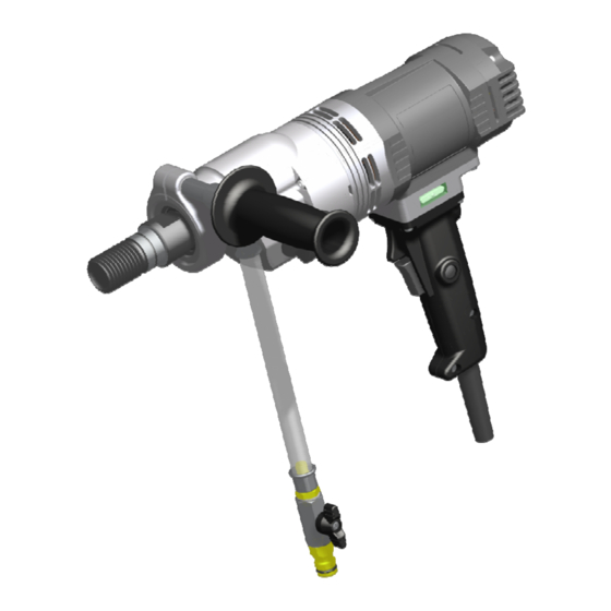
Manual for
drilling motor
EBL 33 F
125 V
Valid from 03.2018
Art.-Nr.
201229
Subject to alteration
All rights reserved
DR. BENDER
GmbH • D-75382 Althengstett • Tel 07051-9291-0 • Fax 07051-9291-91
Our website address is: http://www.dr-bender.de
info@dr-bender.de
• eMail:
Advertisement
Table of Contents

Related Manuals for DR. BENDER EBL 33 F


Summary of Contents for DR. BENDER EBL 33 F
- Page 1 DR. BENDER GmbH Innovative Elektrowerkzeuge Manual for drilling motor EBL 33 F 125 V Valid from 03.2018 Art.-Nr. 201229 Subject to alteration All rights reserved DR. BENDER GmbH • D-75382 Althengstett • Tel 07051-9291-0 • Fax 07051-9291-91 Our website address is: http://www.dr-bender.de info@dr-bender.de...
-
Page 2: Conformity Declaration
Dr. Bender GmbH Industriestrasse 22 75382 Althengstett declares for the product EBL 33 F The named product is conform to the following Council Directives on approximation of laws of the EEC Member States: Council Directive for machinery (2006/42/EC) Council Directive for Electromagnetic compatibility (EMC) (2004/108/EG) -
Page 3: Table Of Contents
Contents page Conformity declaration Contents Symbol- and Pictograph description Function description General instructions Application Safety Transport and storage Transport Storage Main dimensions and technical data Dimensions Technical data Noise emissions and vibrations [EN 50144] Commissioning Changing gear Safety coupling Core bits To change a core bit Safety instructions Servicing and care... -
Page 4: Symbol- And Pictograph Description
Warning The safety instructions set out in this operating manual must be followed at all costs. Special designs and versions may differ from the standard models in terms of their technical de- tails. If any points are unclear, we urgently recommend that you contact DR.BENDER GmbH, indi- cating the machine type and machine number. -
Page 5: General Instructions
General instructions Application Core drilling machines may be used in accordance with the data shown on the model plate. The details in the quotation and order confirmation also apply for the use of special machines. The core drilling machines generally comply with safety class I, this alone ensures the complete protection of the RCCB or PRCD. -
Page 6: Transport And Storage
Transport and storage Transport Warning The core drills are to be checked for signs for transport damage on receipt. Any damage must be documented in writing. Storage If possible, the storage site should be dry, clean and have a constant temperature. To ensure that the film of lubricant in the bearings and sealing system is not lost, the motor shaft should be turned through several revolutions by hand after a lengthy period of storage, for example at monthly intervals. -
Page 7: Main Dimensions And Technical Data
720 / 1890 / 3960 Full speed 450 / 1200 / 2500 Output rating 1590 Torque 36 / 19 / 10 Drilling diameter 20 – 220 Weight EBL 33 F Core bit connection UNC 1 ¼ or R ½ “ Overload coupling torque... -
Page 8: Noise Emissions And Vibrations [En 50144]
Noise emissions and vibrations [EN 50144] Noise level Noise level Vibration dB(A) < 2,5 Commissioning Check that the mains voltage is identical with the voltage specified on the model plate. Stand-mounted: Secure the core drilling machine and the water collection device on the drill stand with a reverse lock. The drill stand should have high rigidity and precise, low-play guides. -
Page 9: Changing Gear
Changing gear Warning Never change gear using force and only do so when the machine is slowing down or at a standstill. Move the gear switch handle by approx. 40° to the next higher or lower gear. If necessary (if it is difficult to engage the gear) turn the drive spindle briefly by hand until the gear engages easily. -
Page 10: Safety Instructions
Safety instructions Important Only use the core drill under supervision. Disconnect the mains plug and check that the switch has been turned off, if you intend to leave the core drill unsupervised, for attachment and disconnection work, if the voltage drops (below 200 V), for adjustments or for fitting an accessory, Switch off the machine if it stops for any reason. -
Page 11: Servicing And Care
Servicing and care Warning Before starting any servicing or repair work always disconnect the mains plug. After all repairs you must have the core drilling machine inspected by an electri- cian (statutory regulation pursuant to VBG4 since 1.1.1990). Daily care Ensure that no water escapes from the overflow hole. -
Page 12: Speed Adjustment Dependent On The Cutting Speed
Speed adjustment dependent on the cutting speed [m/s] 3820 5093 6366 7639 8913 3rd gear 2900 3820 4775 5730 6685 3rd gear 2500 2900 3820 4584 5348 3rd gear 1910 2500 2900 3820 4456 3rd gear 3274 3820 1637 2183 2728 3rd gear 1400... -
Page 13: Warranty
Warranty In keeping with our terms of sale, we offer a warranty for twelve months from the date of sale. This refers to the free repair of material and workmanship defects, which were verifiably caused before the sale. An original purchase document must always be submitted in case of a warranty claim. It has to contain the full address of the dealer, the date of purchase and the type designation of the product. -
Page 14: 10.0 General Safety Instructions
10.0 General safety instructions Read and follow these instructions before you use the tool. Keep these safety instructions in a safe place. Keep your workplace tidy. Untidiness in the workplace can cause accidents. Protect yourself from electric shocks. Refer to the applicable regulations. Avoid physical contact with earthed parts, such as pipes, heaters, furnaces and refrigerators. - Page 15 Check the machine every day for signs of damage, conduct a visual inspection: Before reusing the tool, carefully check the safety equipment or slightly damaged parts to ensure that they offer perfect and proper function. Check that all moving parts function correctly, that they do not jam and that none of the parts are damaged.
-
Page 16: 11.0 Spare Parts List
11.0 Spare parts list 11.1 Stone drilling machine complete... - Page 17 Item Art. No. Description 201229 Stone drilling machine complete 201231 Motor complete 301314 Gear complete 800076 Locking ring 901012 Hexagon socket head cap screw 400961 Handle complete 802980 Water connection complete 1 ** 802981 Hose complete 800028 Sealing ring 800023 Ball cook complete 800020 Slot-in nipple...
-
Page 18: Motor Complete
11.2 Motor complete... - Page 19 Item Art. No. Description 201231 Motor complete 200397 Motor casing 402215 Magnet casing 402164 Distance ring 801426 Brush bridge 800076 Spring washer 900339 Allen bolt 801425 Carbon brush 2 ** 900183 Spring washer 900407 Cheese-head screw 900231 Washer 900181 Wave spring washer 900412 Flat head screw 401101...
-
Page 20: 11.3 Gear Complete
11.3 Gear complete... - Page 21 Item Art. No. Description 301314 Gear complete 200570 Gear casing 900486 Grooved ball bearing 1 ** 800483 Compensation slice 100723 Control grip 801367 O ring 401038 Sleeve 401036 Switch handle complete 801755 Slotted cheese head screws 900020 Shaft sealing ring 1 ** 900019 Shaft sealing ring...
-
Page 22: Connection Cables And Accessories
11.4 Connection cables and accessories... - Page 23 Item Article number Description Plugs for UK and standards for type EBM 801462 Connection cable compl. 4h 900159 Plug, 4h 801328 Connection cable, finished Plugs for UK and standards for type BBM 801460 Connection cable compl. 4h 900159 Plug, 4h 801459 Connection cable, finished Plugs for USA and Japan up to 30 amps for type BBM...
Need help?
Do you have a question about the EBL 33 F and is the answer not in the manual?
Questions and answers