Table of Contents
Advertisement
Quick Links
DR. BENDER
GmbH
Innovative Elektrowerkzeuge
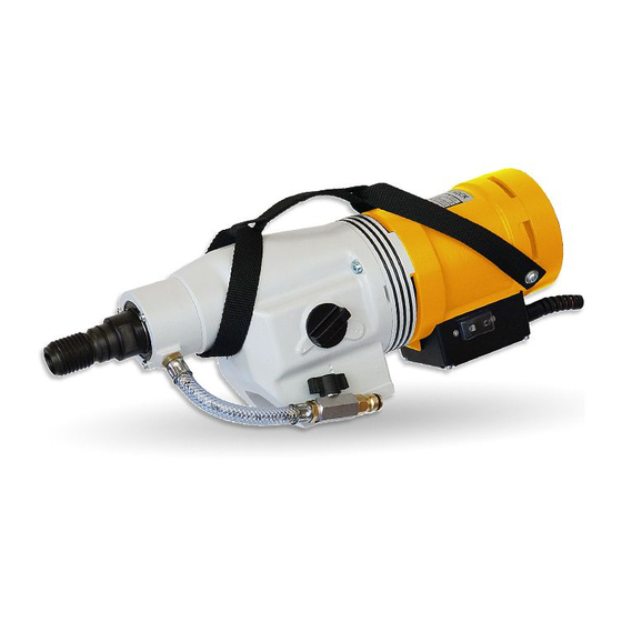
Manual for
drilling motor
BBM 33 LL extra
125 V
Valid from 03.2018
Art.-Nr.
201218
Subject to alteration
All rights reserved
DR. BENDER
GmbH • D-75382 Althengstett • Tel 07051-9291-0 • Fax 07051-9291-91
Our website address is: http://www.dr-bender.de
info@dr-bender.de
• eMail:
Advertisement
Table of Contents

Related Manuals for DR. BENDER BBM 33 LL extra


Summary of Contents for DR. BENDER BBM 33 LL extra
- Page 1 DR. BENDER GmbH Innovative Elektrowerkzeuge Manual for drilling motor BBM 33 LL extra 125 V Valid from 03.2018 Art.-Nr. 201218 Subject to alteration All rights reserved DR. BENDER GmbH • D-75382 Althengstett • Tel 07051-9291-0 • Fax 07051-9291-91 Our website address is: http://www.dr-bender.de info@dr-bender.de...
-
Page 2: Conformity Declaration
Dr. Bender GmbH Industriestrasse 22 75382 Althengstett declares for the product BBM 33 LL extra The named product is conform to the following Council Directives on approximation of laws of the EEC Member States: Council Directive for machinery (2006/42/EC) Council Directive for Electromagnetic compatibility (EMC) (2004/108/EG) -
Page 3: Table Of Contents
Contents page Conformity declaration Contents Symbol- and Pictograph description Function description General instructions Application Safety Transport and storage Transport Storage Main dimensions and technical data Dimensions Technical data Noise emissions and vibrations [EN 50144] Commissioning Changing gear Safety coupling Core bits To change a core bit Safety instructions Servicing and care... -
Page 4: Symbol- And Pictograph Description
Warning The safety instructions set out in this operating manual must be followed at all costs. Special designs and versions may differ from the standard models in terms of their technical details. If any points are unclear, we urgently recommend that you contact DR.BENDER GmbH, indicating the machine type and machine number. -
Page 5: General Instructions
General instructions Application The core drills can be used for the purposes outlined by the data on the model plate. If you are using spe- cial machines, the details in the quotation and order confirmation also apply. The core drills are supplied as standard in protection class I, only this can guarantee the full high quality production of the residual current-operated circuit-breaker or PRCD switch. -
Page 6: Transport And Storage
Transport and storage Transport Warning The core drills are to be checked for signs for transport damage on receipt. Any damage must be documented in writing. Storage If possible, the storage site should be dry, clean and have a constant temperature. To ensure that the film of lubricant in the bearings and sealing system is not lost, the motor shaft should be turned through several revolutions by hand after a lengthy period of storage, for example at monthly intervals. -
Page 7: Main Dimensions And Technical Data
Main dimensions and technical data Dimensions Technical data Rated Voltage Current consumption Power requirement 3300 Frequency 50 – 60 Idling speed 315 / 720 / 1090 Full speed 155 / 375 / 650 Output rating 2400 Torque 142 / 68 / 38 Drilling diameter 50 - 470 Weight... -
Page 8: Noise Emissions And Vibrations [En 50144]
Noise emissions and vibrations [EN 50144] Noise level Noise level Vibration dB(A) < 2,5 Commisioning Check that the mains voltage is identical to the voltage specified on the model plate. Secure the core drill and the water collector to the drilling stand with its reverse block. The drilling stand should be as rigid as possible and have precise, low-play guides. -
Page 9: Changing Gear
Changing gear Warning Never change gear using force and only do so when the machine is slowing down or at a standstill. To change into the next higher or lower gear, move the gear-change lever through an angle of approx. 50°. If necessary (if the gear is difficult to engage), turn the drive spindle briefly by hand until the gear engages easily. -
Page 10: Safety Instructions
Safety instructions Important Only use the core drill under supervision. Disconnect the mains plug and check that the switch has been turned off, - If you intend to leave the core drill unsupervised, - For attachment and disconnection work, - If the voltage drops (below 340 V), - At uneven mains voltage (phase asymetrical) or interruption of a phase (phase failure), - For adjustments or for fitting an accessory, Switch off the machine if it stops for any reason. -
Page 11: Servicing And Care
Servicing and care Warning Before starting any servicing or repair work always disconnect the mains plug. After all repairs you must have the core drilling machine inspected by an elec- trician (statutory regulation pursuant to VBG4 since 1.1.1990). Daily care Ensure that no water is emitted from the overflow hole. -
Page 12: Speed Adjustment Dependent On The Cutting Speed
8.0 Speed adjustment dependent on the cutting speed [m/s] 1146 1528 1910 2292 2674 3rd gear 1273 1592 1910 2228 3rd gear 1175 3rd gear 1469 1763 2057 1091 1364 1637 1910 3rd gear 1019 1273 1528 1783 3rd gear 1194 1432 1671... -
Page 13: Warranty
Warranty In keeping with our terms of sale, we offer a warranty for twelve months from the date of sale. This refers to the free repair of material and workmanship defects, which were verifiably caused before the sale. An original purchase document must always be submitted in case of a warranty claim. It has to contain the full address of the dealer, the date of purchase and the type designation of the product. -
Page 14: Spare Parts List
11.0 Spare parts list 11.1 Stone drilling machine complete... - Page 15 Item Art. No. Description 201218 Stone drilling machine complete 301277 Motor complete 200895 Gear complete 300074 Water connection complete 1 ** 800733 Hose complete 800028 Sealing ring 800023 Ball cook complete 800020 Slot-in nipple 800040 O-ring 800077 Locking ring 900318 Hexagon socket head cap screw Wearing parts**...
-
Page 16: Motor Complete
11.2 Motor complete... - Page 17 Item Art. No. Description 301277 Motor complete 200839 Motor casing 401554 Field coil 900011 Set screw 900229 Washer 800076 Locking washer 900412 Slotted pan head screw 300068 Brush bridge 800064 Carbon brush 2 ** 900180 Locking washer 900332 Hexagon socket head cap screw 900183 Wave spring washer 900399...
-
Page 18: Gear Complete
11.3 Gear complete... - Page 19 Item Art. No. Description 301764 Gear complete 100080 Gear casing 900051 Grooved ball bearings 1 ** 900495 Grooved ball bearings 1 ** 900670 Interim washer 400795 Sleeve 900669 Axial needle rim 2 ** 900672 Rotor disc 2 ** 900671 Needle bearing 1 ** 300670 Support disc...
-
Page 20: Connection Cables And Accessories
11.4 Connection cables and accessories... - Page 21 Item Article number Description Plugs for UK and standards for type EBM 801462 Connection cable compl. 4h 900159 Plug, 4h 801328 Connection cable, finished Plugs for UK and standards for type BBM 801460 Connection cable compl. 4h 900159 Plug, 4h 801459 Connection cable, finished Plugs for USA and Japan up to 30 amps for type BBM...
Need help?
Do you have a question about the BBM 33 LL extra and is the answer not in the manual?
Questions and answers