Table of Contents
Advertisement
Quick Links
DR. BENDER
GmbH
Innovative Elektrowerkzeuge
Manual for
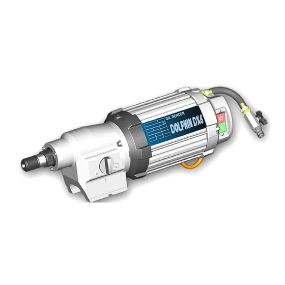
DX 6 Dolphin
drilling motor
400 V
3~
Valid from 09.2004
Art.-Nr.
200674
Subject to alterations
Alle Rechte vorbehalten / All rights reserved
DR. BENDER
GmbH • D-75382 Althengstett • Tel 07051-9291-0 • Fax 07051-9291-91
info@dr-bender.de
Our website address is: http://www.dr-bender.de
• eMail:
Advertisement
Table of Contents

Related Manuals for DR. BENDER DX 6 DOLPHIN


Summary of Contents for DR. BENDER DX 6 DOLPHIN
- Page 1 DR. BENDER GmbH Innovative Elektrowerkzeuge Manual for DX 6 Dolphin drilling motor 400 V Valid from 09.2004 Art.-Nr. 200674 Subject to alterations Alle Rechte vorbehalten / All rights reserved DR. BENDER GmbH • D-75382 Althengstett • Tel 07051-9291-0 • Fax 07051-9291-91 info@dr-bender.de...
-
Page 2: Conformity Declaration
GmbH Innovative Elektrowerkzeuge EC Conformity Declaration for DR.BENDER stone processing machine DX 6 Dolphin DR.BENDER GmbH, as manufacturer, hereby declares that the electrical stone processing machine men- tioned above comply with the requirements of the following guidelines: Machine guidelines (98/37/EC) -
Page 3: Table Of Contents
Contents page Conformity declaration Contents Symbol- and Pictograph description Function description General instructions Application Safety Transport and storage Transport Storage Main dimensions and technical data Dimensions Technical data Noise emissions and vibrations [EN 50144] Commissioning Changing gear Safety coupling Core bits To change a core bit Safety instructions Servicing and care... -
Page 4: Symbol- And Pictograph Description
Warning It is compulsory to observe the safety instructions included in this manual! Special designs and versions may differ from the standard models in terms of their technical de- tails. If any points are unclear, we urgently recommend that you contact DR.BENDER GmbH, indi- cating the machine type and machine number. -
Page 5: General Instructions
General instructions Application The core drills can be used for the purposes outlined by the data on the model plate. If you are using spe- cial machines, the details in the quotation and order confirmation also apply. The core drills are supplied as standard in protection class I, only this can guarantee the full high quality production of the residual current-operated circuit-breaker or PRCD switch. -
Page 6: Transport And Storage
Transport and storage Transport Warning The core drills are to be checked for signs for transport damage on receipt. Any damage must be documented in writing. Storage If possible, the storage site should be dry, clean and have a constant temperature. To ensure that the film of lubricant in the bearings and sealing system is not lost, the motor shaft should be turned through several revolutions by hand after a lengthy period of storage, for example at monthly intervals. -
Page 7: Main Dimensions And Technical Data
Main dimensions and technical data Dimensions Technical data Rated voltage Current consumption 10,5 Power requirement 6000 Frequency 50 – 60 Idling speed 160 / 430 / 750 Full speed 160 / 430 / 750 Output rating 4200 Torque 280 / 120 / 65 Drilling diameter 100 –... -
Page 8: Noise Emissions And Vibrations [En 50144]
Noise emissions and vibrations [EN 50144] Noise level Noise level Vibration dB(A) < 2,5 Commissioning Check that the mains voltage is identical to the voltage specified on the model plate. Secure the core drill and the water collector to the drilling stand with its reverse block. The drilling stand should be as rigid as possible and have precise, low-play guides. -
Page 9: Changing Gear
Changing gear Warning Never change gear using force and only do so when the machine is slowing down or at a standstill. To change into the next higher or lower gear, move the gear-change lever through an angle of approx. 50°. If necessary (if the gear is difficult to engage), turn the drive spindle briefly by hand until the gear engages easily. -
Page 10: Safety Instructions
Safety instructions Important Only use the core drill under supervision. Disconnect the mains plug and check that the switch has been turned off, if you intend to leave the core drill unsupervised, for attachment and disconnection work, if the voltage drops (below 340 V), at uneven mains voltage (phase asymetrical) or interruption of a phase (phase failure), for adjustments or for fitting an accessory, Switch off the machine if it stops for any reason. -
Page 11: Servicing And Care
Servicing and care Warning Disconnect the mains plug before commencing any servicing or repair work. You must have the core drill checked by an electrician after every repair (statu- tory regulation pursuant to VBG4 since 1.1.1990). Daily care Ensure that no water is emitted from the overflow hole. This will cause gear damage and may adversely affect the electrical safety of the core drill. -
Page 12: Speed Adjustment Dependent On The Cutting Speed
Speed adjustment dependent on the cutting speed [m/s] 1091 1364 1637 1910 3rd gear 1194 1432 1671 3rd gear 1061 1273 1485 3rd gear 1146 1337 3rd gear 1042 1215 3rd gear 1114 3rd gear 1028 3rd gear 3rd gear 3rd gear 3rd gear 3rd gear... -
Page 13: Warranty
Warranty In keeping with our terms of sale, we offer a warranty for six months from the date of sale. This refers to the free repair of material and workmanship defects, which were verifiably caused before the sale. An original purchase document must always be submitted in case of a warranty claim. It has to contain the full address of the dealer, the date of purchase and the type designation of the product. -
Page 14: General Safety Instructions
10.0 General safety instructions Read and follow these instructions before you use the tool. Keep these safety instructions in a safe place. Keep your workplace tidy. Untidiness in the workplace can cause accidents. Protect yourself from electric shocks. Refer to the applicable regulations. Avoid physical contact with earthed parts, such as pipes, heaters, furnaces and refrigerators. - Page 15 Check the machine every day for signs of damage, conduct a visual inspection: Before reusing the tool, carefully check the safety equipment or slightly damaged parts to ensure that they offer perfect and proper function. Check that all moving parts function correctly, that they do not jam and that none of the parts are damaged.
-
Page 16: Spare Parts List
11.0 Spare parts list 11.1 Motor complete... - Page 17 Item Art. No. Description 300993 Motor compl. 200675 Motor casing 401201 Stoppers 801375 Stator 401200 Thick hull 801384 O Ring 4 ** 300996 Rotor compl. 800757 Grooved ball bearings 1 ** 900202 Spring washer 1 ** 900679 Grooved ball bearings 1 ** 200676 Intermediate cover...
-
Page 18: Gear Complete
11.2 Gear complete... - Page 19 Item Art. No. Description 200678 Gear, complete 100067 Gear casing 900051 Grooved ball bearings 1 ** 900495 Grooved ball bearings 1 ** 401342 Interim washer 401343 Sleeve 900669 Axial needle rim 2 ** 401345 Interim washer 900671 Needle bearing 1 ** 900672 Rotor disc 300670...
-
Page 20: Connection Cables And Accessories
11.3 Connection cable and accessories... - Page 21 Item Article number Description Plugs for Germany, France, Italy softstart 801387 Connection cable compl. 401233 Plug with integrated softstart, 16 A 801465 Connection cable, finished Plugs phase reversal 801466 Connection cable compl. 900164 Plug, 6h, phase reversal, 16 A 801467 Connection cable, finished Plugs 801163...
- Page 22 From our product spectrum...
Need help?
Do you have a question about the DX 6 DOLPHIN and is the answer not in the manual?
Questions and answers