
Related Manuals for GEM BioStar 567


Summary of Contents for GEM BioStar 567
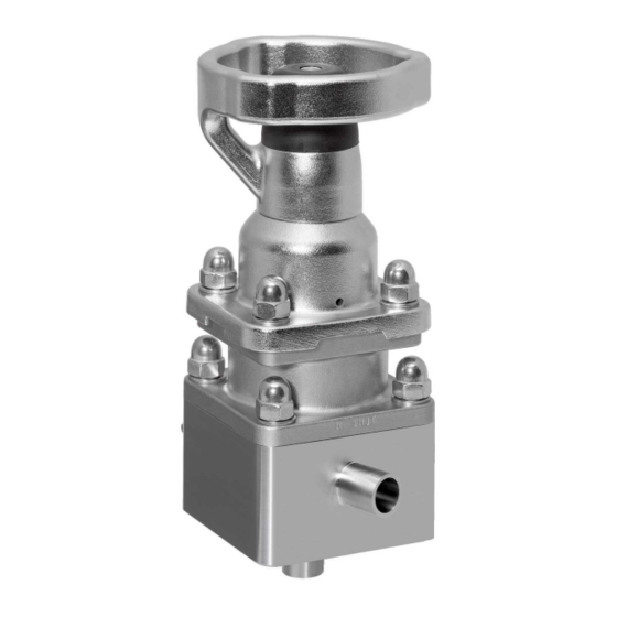
- Page 1 GEMÜ 567 BioStar control Manually operated control valve Operating instructions further information webcode: GW-567...
- Page 2 All rights including copyrights or industrial property rights are expressly reserved. Keep the document for future reference. © GEMÜ Gebr. Müller Apparatebau GmbH & Co. KG 23.11.2022 GEMÜ 567 BioStar control 2 / 44 www.gemu-group.com...
-
Page 3: Table Of Contents
8 Mounting ............. 9 Troubleshooting ..........10 Inspection and maintenance ........ 11 Removal from piping ..........12 Disposal .............. 13 Returns ..............14 Declaration of conformity according to 2014/68/ EU (Pressure Equipment Directive) ...... www.gemu-group.com 3 / 44 GEMÜ 567 BioStar control... -
Page 4: General Information
Potentially dangerous situation! 1.3 Definition of terms ▶ Non-observance can cause death or severe injury. Working medium The medium that flows through the GEMÜ product. CAUTION PD = Plug Diaphragm Potentially dangerous situation! ▶ Non-observance can cause moderate to light injury. -
Page 5: Product Description
80 l/h to 12,500 l/h, depending on the version. The Item Name Materials sealing concept of the valve is based on the GEMÜ PD design. All actuator parts (except the seals) are made from stainless Plug diaphragm PTFE steel. - Page 6 Actuator horizontal or vertical Control range We recommend designing the valves in such a way that the control range is within an opening stroke of 20% to 90% of the control valve. GEMÜ 567 BioStar control 6 / 44 www.gemu-group.com...
-
Page 7: Order Data
54 Actuator size 2, 7 Control function Code plastic handwheel, without seal adjuster and stroke limiter Manually operated Actuator size 2, plastic handwheel, with seal adjuster and stroke limiter www.gemu-group.com 7 / 44 GEMÜ 567 BioStar control... - Page 8 160 l/h 250 l/h 400 l/h 630 l/h 1.0 m³/h 1.6 m³/h 2.6 m³/h 4.1 m³/h 8.0 m³/h 12.5 m³/h 11 Bypass actuator version Code Pneumatically operated, normally closed, diaphragm size 8, GEMÜ 567 BioStar control 8 / 44 www.gemu-group.com...
- Page 9 Ra ≤ 0.4 µm (15 µin.) for media wetted surfaces, in accordance with DIN 11866 H4, mechanically polished internal 13 Special version Special version for 3A 14 CONEXO Integrated RFID chip for electronic identification and traceability www.gemu-group.com 9 / 44 GEMÜ 567 BioStar control...
-
Page 10: Technical Data
This also applies to PTFE diaphragms exposed to high temperature fluctuations. The mainten- ance cycles must be adapted accordingly. Ambient temperature: -10 to 60 °C Storage temperature: 0 — 40 °C 4.3 Pressure Operating pressure: Pressure/Temperature diagram -20 -10 0 Temperature [°C] GEMÜ 567 BioStar control 10 / 44 www.gemu-group.com... - Page 11 GDH, LDH 1.6 m³/h GEJ, LEJ 2.6 m³/h GG1, LG1 4.1 m³/h GH2, LH2 8.0 m³/h GJ3, LJ3 12.5 m³/h Kv values of bypass 2.1 m³/h Kv values determined acc.to DIN EN 60534. www.gemu-group.com 11 / 44 GEMÜ 567 BioStar control...
- Page 12 2006/42/EC EMC Directive: 2014/30/EU Food: USP Class VI Regulation (EC) No. 1935/2004 Regulation (EC) No. 10/2011 4.5 Mechanical data Weight: Valve assembly Actuator version 2 2.4 kg Actuator version 3 7.8 kg GEMÜ 567 BioStar control 12 / 44 www.gemu-group.com...
-
Page 13: Dimensions
5 Dimensions 5 Dimensions 5.1 Actuator dimensions ØB Actuator size ØB 8, 10, 15, 20 135.0 90.0 20, 25 193.0 114.0 Dimensions in mm * CT = A + H1 (see body dimensions) www.gemu-group.com 13 / 44 GEMÜ 567 BioStar control... - Page 14 25.0 20.0 54.0 26.0 50.0 22.0 55.0 95.0 25.0 20.0 54.0 26.0 50.0 28.0 55.0 95.0 25.0 25.0 54.0 26.0 47.5 28.0 Dimensions in mm 1) Connection type Code 0: Spigot DIN GEMÜ 567 BioStar control 14 / 44 www.gemu-group.com...
- Page 15 26.5 50.5 29.0 55.0 95.0 25.0 25.0 53.5 26.5 48.0 29.0 Dimensions in mm 1) Connection type Code 17: Spigot EN 10357 series A (formerly DIN 11850 series 2)/DIN 11866 series A www.gemu-group.com 15 / 44 GEMÜ 567 BioStar control...
- Page 16 43.6 21.4 37.88 0.38 19.05 1.65 55.0 95.0 25.0 20.0 55.4 24.6 48.60 1.10 25.40 1.65 Dimensions in mm 1) Connection type Code 59: Spigot ASME BPE / DIN 11866 series C GEMÜ 567 BioStar control 16 / 44 www.gemu-group.com...
- Page 17 20.0 54.6 28.4 52.40 4.90 33.7 55.0 95.0 25.0 25.0 51.6 28.4 49.90 2.40 33.7 Dimensions in mm 1) Connection type Code 60: Spigot ISO 1127/EN 10357 series C/DIN 11866 series B www.gemu-group.com 17 / 44 GEMÜ 567 BioStar control...
- Page 18 42.0 18.0 53.0 75.0 20.0 52.0 21.0 41.0 18.0 53.0 75.0 20.0 10.0 52.0 21.0 40.0 18.0 53.0 75.0 20.0 15.0 52.0 21.0 37.5 18.0 1) Connection type Code 0: Spigot DIN GEMÜ 567 BioStar control 18 / 44 www.gemu-group.com...
- Page 19 21.5 40.5 19.0 53.0 75.0 20.0 15.0 51.5 21.5 38.0 19.0 Dimensions in mm 1) Connection type Code 17: Spigot EN 10357 series A (formerly DIN 11850 series 2)/DIN 11866 series A www.gemu-group.com 19 / 44 GEMÜ 567 BioStar control...
- Page 20 51.6 21.4 40.38 2.88 19.05 1.65 53.0 75.0 20.0 15.0 51.6 21.4 37.88 0.38 19.05 1.65 Dimensions in mm 1) Connection type Code 59: Spigot ASME BPE / DIN 11866 series C GEMÜ 567 BioStar control 20 / 44 www.gemu-group.com...
- Page 21 10.0 50.4 22.6 41.55 4.05 21.3 53.0 75.0 20.0 15.0 50.4 22.6 39.05 1.55 21.3 Dimensions in mm 1) Connection type Code 60: Spigot ISO 1127/EN 10357 series C/DIN 11866 series B www.gemu-group.com 21 / 44 GEMÜ 567 BioStar control...
- Page 22 95.0 20.0 62.6 90.40 30.4 52.40 4.90 25.0 50.5 55.0 95.0 25.0 62.6 87.90 30.4 49.90 2.40 25.0 50.5 Dimensions in mm 1) Connection type Code 82: Clamp DIN 32676 series B GEMÜ 567 BioStar control 22 / 44 www.gemu-group.com...
- Page 23 34.0 55.0 95.0 20.0 65.0 88.0 28.1 50.0 26.0 50.5 55.0 95.0 25.0 65.0 88.5 28.1 47.5 26.0 50.5 Dimensions in mm 1) Connection type Code 86: Clamp DIN 32676 series A www.gemu-group.com 23 / 44 GEMÜ 567 BioStar control...
- Page 24 25.0 45.0 75.0 15.0 56.5 70.88 21.4 37.88 0.38 15.75 25.0 55.0 95.0 20.0 66.8 87.60 26.3 48.60 1.10 22.10 50.5 Dimensions in mm 1) Connection type Code 88: Clamp ASME BPE GEMÜ 567 BioStar control 24 / 44 www.gemu-group.com...
- Page 25 75.0 10.0 63.4 74.55 22.6 41.55 4.05 18.1 50.5 53.0 75.0 15.0 63.4 72.05 22.6 39.05 1.55 18.1 50.5 Dimensions in mm 1) Connection type Code 82: Clamp DIN 32676 series B www.gemu-group.com 25 / 44 GEMÜ 567 BioStar control...
- Page 26 34.0 53.0 75.0 10.0 64.5 73.5 21.5 40.5 16.0 34.0 53.0 75.0 15.0 64.5 71.0 21.5 38.0 16.0 34.0 Dimensions in mm 1) Connection type Code 86: Clamp DIN 32676 series A GEMÜ 567 BioStar control 26 / 44 www.gemu-group.com...
- Page 27 25.0 53.0 75.0 10.0 64.6 73.38 21.4 40.38 2.88 15.75 25.0 53.0 75.0 15.0 64.6 70.88 21.4 37.88 0.38 15.75 25.0 Dimensions in mm 1) Connection type Code 88: Clamp ASME BPE www.gemu-group.com 27 / 44 GEMÜ 567 BioStar control...
-
Page 28: Manufacturer's Information
We recommend designing the valves in such a way that the 4. Do not store solvents, chemicals, acids, fuels or similar control range is within an opening stroke of 20% to 90% of the fluids in the same room as GEMÜ products and their spare control valve. parts. -
Page 29: Installation With Clamp Connections
13. Only install the product between matching aligned pipes (see chapters below). 14. Please note the flow direction (see chapter "Flow direc- tion"). 15. Please note the installation position (see chapter "Installa- tion position"). www.gemu-group.com 29 / 44 GEMÜ 567 BioStar control... -
Page 30: Mounting
▶ Important: Incorrectly mounted diaphragm may cause valve leakage / emission of medium. In this case remove the diaphragm, check the complete valve and diaphragm and reassemble again proceeding as described above. GEMÜ 567 BioStar control 30 / 44 www.gemu-group.com... - Page 31 ð Take care to align the compressor weir and valve body weir (diaphragm size 8). 3. Tighten the fastening elements by hand. 4. Move the actuator to the closed position. 5. Fully tighten the bolts with nuts diagonally www.gemu-group.com 31 / 44 GEMÜ 567 BioStar control...
-
Page 32: Troubleshooting
Check installation of valve body in piping ing leaking Sealing material faulty Replace sealing material Valve body leaking Valve body leaking or corroded Check valve body for damage, replace valve body if necessary GEMÜ 567 BioStar control 32 / 44 www.gemu-group.com... -
Page 33: Inspection And Maintenance
4. Secure the plant or plant component against recommis- sioning. 5. Depressurize the plant or plant component. 6. Actuate GEMÜ products which are always in the same po- sition four times a year. 10.1 Replacing the actuator 10.1.1 Remove the actuator from the distance piece. - Page 34 30-35 Nm ● 40 Nm CAUTION 70 Nm Use of incorrect spare parts! ▶ Damage to the GEMÜ product. ▶ Manufacturer liability and guarantee will be void. Use only genuine parts from GEMÜ. ● CAUTION Valve is no longer functioning correctly ▶...
- Page 35 9. Carefully remove the solvent cement from the thread on the regulating cone 3 (e.g. using a stainless steel brush). ð Do not damage the regulating cone surface in the pro- cess. www.gemu-group.com 35 / 44 GEMÜ 567 BioStar control...
- Page 36 3. Screw the regulating cone 3 into the support ring 20 until it 9. Tighten the cap nuts 18 diagonally. is hand tight. Actuator size Tightening torque 16-20 Nm 30-35 Nm GEMÜ 567 BioStar control 36 / 44 www.gemu-group.com...
- Page 37 10.4.1 Removing the plug diaphragm 70 Nm CAUTION Use of incorrect spare parts! ▶ Damage to the GEMÜ product. ▶ Manufacturer liability and guarantee will be void. 10.3 Replacing the plug diaphragm (code 4) Use only genuine parts from GEMÜ.
- Page 38 If parts are damaged, replace them. ü Actuator size 4/5: Press valve spindle 6 downwards to 2. Use only genuine parts from GEMÜ. screw in the plug diaphragm 2 completely. 10.5.3 Mounting the diaphragm 1. Screw the plug diaphragm 2 to the valve spindle 6 and hand-tighten it.
- Page 39 10.6 Cleaning the product - Clean the product with a damp cloth. - Do not clean the product with a high pressure cleaning device. www.gemu-group.com 39 / 44 GEMÜ 567 BioStar control...
- Page 40 Valve body K567 Plug diaphragm 567 SVS… O-ring Plug diaphragm 567 SVM... O-ring Assembly tool Plug diaphragm 567 SRK 4... Regulating cone O-ring Assembly tool Set of screws (88491207) 567 S30E 41 2 GEMÜ 567 BioStar control 40 / 44 www.gemu-group.com...
- Page 41 10 Inspection and maintenance 10.7.2 Seal material code 5, 55 Item Name Order description Actuator 9567 Valve body K567 Plug diaphragm with regulating cone 567 SRK 5… Set of screws (88491207) 567 S30E 41 2 www.gemu-group.com 41 / 44 GEMÜ 567 BioStar control...
-
Page 42: Removal From Piping
If suitable cutting tool. no return delivery note is included with the product, GEMÜ 3. Observe the safety information and accident prevention cannot process credits or repair work but will dispose of the regulations. -
Page 43: Declaration Of Conformity According To 2014/68/Eu (Pressure Equipment Directive)
Pressure Equipment Directive 2014/68/EU. Note for products with a nominal size ≤ DN 25: The products are developed and produced according to GEMÜ process instructions and quality standards which comply with the requirements of ISO 9001 and ISO 14001. - Page 44 GEMÜ Gebr. Müller Apparatebau GmbH & Co. KG Fritz-Müller-Straße 6-8, 74653 Ingelfingen-Criesbach, Germany Subject to alteration Phone +49 (0) 7940 1230 · info@gemue.de www.gemu-group.com 11.2022 | 88658294...
Need help?
Do you have a question about the BioStar 567 and is the answer not in the manual?
Questions and answers