Advertisement
Quick Links
MALLORY FIRESTORM CD MULTI COIL HARDWARE
INSTALLATION - PN 69050S / 69050R
To ensure you are using the most current instruction sheet, please visit www.malloryfirestorm.com.
The SMART coil secondary outputs extremely high voltage. Make sure to avoid contact with the
tower and or plug wire during key on, and while the vehicle is running or serious injury can result.
Always make sure the battery is disconnected during installation and maintenance.
PARTS INCLUDED:
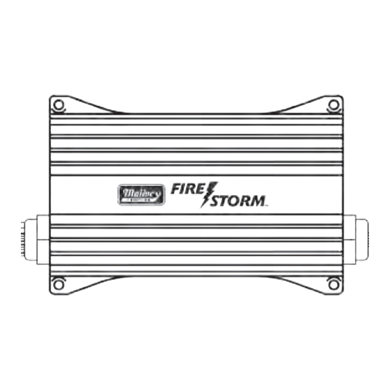
FireStorm Ignition Module
Main Harness
Coil Harness
8 pin Flying lead adapter harness
10 pin accessory harness (69050R only. 69050S optional)
Software Installation CD
Hardware kit
GENERAL INFORMATION
Battery
This Ignition Control Module operates on any negative ground, 12 volt
electrical system with a distributor. It will also work with 16 volt bat-
teries. If your application does not use an alternator, allow at least 15
amp/hour for every half hour of operation. If you crank the engine with
the same battery or other accessories, such as an electric fuel or water
pump, increase the amp/hour rating.
Coils
For optimum performance with your Ignition Control Module, use
matching coil such as MALLORY Firestorm (140053 Bottom Tower or
140054 Side Tower).
Using the correct spark plug and heat range is important for optimum
performance. Because there are so many variables to consider, we
suggest starting with your engine manufacturer's spark plug recom-
mendation. From there, you can experiment with small changes in plug
gap and heat range to obtain the best performance from your engine.
We also recommend non-resistor spark plugs.
Spark Plug Wires
High quality, spark plug wires with a resistance rating of no less than
500 ohms/ft, and proper routing are essential to the operation of the
Firestorm Ignition Control Module. This type of wire provides a good
path for the spark to follow while minimizing electromagnetic interfer-
ence (EMI). NOTE: Do not use solid core spark plug wires with this
Ignition Control.
Routing
Wires should be routed away from sharp edges, moving objects, and
heat sources. For added protection MALLORY offers PRO SLEEVE (P/
N836). Pro Sleeve is a glass woven, silicone coated protective sleeve
that slides over your plug wires and helps reduce damage from heat
and sharp objects.
Welding
To avoid any damage to the Ignition Control Module when welding
MALLORY
CAUTION!
on the vehicle, disconnect the main positive (red) and negative (black)
power cables of the Ignition Control Module. It is also a good idea to
disconnect the tachometer ground wire as well.
MISCELLANEOUS INFORMATION
Sealing
Do not attempt to seal the Ignition Control Module. All of the circuits
receive a conformal coating of sealant that protects the electronics
from moisture. Sealing the Ignition will not allow any moisture that
seeps in through the grommets to drain and may result in corrosion.
WIRING
Wire Length
All of the wires of the Ignition Control Module may be shortened as
long as quality connectors are used or soldered in place. To lengthen
the wires, use one size larger gauge wire (12 gauge for power leads, 16
gauge for all others). Use the proper connectors to terminate all wires.
All connections must be soldered and sealed.
Grounds
A poor ground connection can cause many frustrating problems. When a
wire is specified to go to ground, connect it to the chassis. Always con-
nect a ground strap between the engine and chassis. Connect any ground
wires including shield ground wires to a clean, paint-free metal surface.
Module Installation:
Ensure that the ignition key is off and disconnect the battery. Deter-
mine a suitable mounting location for the Firestorm module such as a
fenderwell or firewall, to minimize exposure to heat, moisture and mov-
ing parts. Make sure all wires reach their connections. The Firestorm
Ignition Control Module can be mounted in any position, but should not
be mounted in an enclosed area such as the glovebox. Once a suitable
mounting location is determined, hold the module in place and mark
the location of the mounting holes. Use a 1/8" drill bit to drill the holes
and use the supplied self tapping screws to mount the box.
Wiring connections:
Refer to the wiring illustrations below for your specific application.
www.malloryfirestorm.com
FORM 69050S/R
1
Advertisement

Related Manuals for Mallory FIRE STORM 69050S


Summary of Contents for Mallory FIRE STORM 69050S
- Page 1 Coils For optimum performance with your Ignition Control Module, use WIRING matching coil such as MALLORY Firestorm (140053 Bottom Tower or 140054 Side Tower). Wire Length All of the wires of the Ignition Control Module may be shortened as Using the correct spark plug and heat range is important for optimum long as quality connectors are used or soldered in place.
- Page 2 Mallory Even 77640 and Odd 77641 coil harnesses. coil harnesses. (The GM or Mallory SMART coil harnesses are a direct plug in) Shield ground - Connect to a good, clean chassis ground to minimize Trigger Inputs EMI noise.
-
Page 3: Routing Wires
Eastern Time. use proper connections followed by soldering, then seal the connec- tions completely. Help for any parameter in the Mallory SparkMap software, can be ac- Checking for Spark cessed by clicking on the parameter name and pressing F1. - Page 4 MALLORY...
- Page 5 MALLORY IGNITION IS A TRADEMARK OF PRESTOLITE PERFORMANCE FORM 69050S/R 06/12 10601 Memphis Ave. #12, Cleveland, OH 44144 Made in U.S.A. 216.688.8300 FAX 216.688.8306 Printed in U.S.A. MALLORY www.malloryfirestorm.com...