Table of Contents
Advertisement
Quick Links
- 1 Ignition Coils
- 2 Early Model Gm Hei Systems (Non-Computer Type, Without Module)
- 3 Wiring Procedure
- 4 Ford Tfi Systems
- 5 Advance Distributors (3-Wire/Red, Brown, Green)
- 6 Top Panel Operation and Features
- 7 Pickup Distributors or Crank Trigger Ignition)
- 8 Ignition System (Pn 685 Only)
- Download this manual
Advertisement
Table of Contents

Related Manuals for Mallory HYFIRE VI Series


Summary of Contents for Mallory HYFIRE VI Series
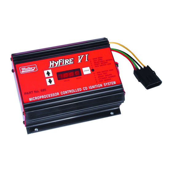
- Page 1 HYFIRE® VI Series Electronic Ignition Controls Instruction Manual Part#: 685, 6851...
-
Page 2: Table Of Contents
VI Ignition System Part No. 6851, Basic ® For applications triggered by points, Mallory Electronic Ignition Distributor (all models), original equipment electronic ignition amplifi ers and magnetic trigger pulses (magnetic pickup distributor or crank trigger ignition). Optional adapters are available for easy connection to early model Delco/GM HEI Systems, late model GM HEI/EST Systems, Ford TFI Systems, and OEM magnetic pickup (non-computer;... -
Page 3: General Information
(if possible) before any welding is done on the vehicle. External RPM Limiters Mallory Proportional RPM Limiter Part Nos. 641-4, 641-6, 641-8, 642, 643 and 644 WILL NOT function with the HYFIRE VI Electronic Ignition Controls. -
Page 4: Wiring Procedure
BASIC WIRING PROCEDURE Step 1 Refer to Figure 2 Ensure that your vehicle is equipped with a ground cable between the engine block and fi rewall PART NO. 29062 – Connecting to Ford TFI Systems. (10 gauge or larger is required). Locate the harness with the LONG RED WIRE and one LONG PART NOS. - Page 5 FIGURE 4 MALLORY 8MM SUPPRE ® FIGURE 5 ® FIGURE 6 ®...
- Page 6 FIGURE 7 ® FIGURE 8 ®...
- Page 7 Connecting to Ford DuraSpark Systems (non-computer type) using Adapter PART For coil-in-cap distributors only NO. 29039 and Harness PART NO. 29040 for OEM magnetic pickup Refer to Figure 10 while performing the following steps. Refer to Figure 8 while performing the following steps. •...
-
Page 8: Advance Distributors (3-Wire/Red, Brown, Green)
• Similarly, disconnect ALL wires located on the ignition coil (–) terminal. Connect these wires to the GREEN WIRE. If you are using a Mallory Electronic Ignition, add its GREEN WIRE • Connect the BLACK WIRE to the ignition coil (–) terminal. - Page 9 FIGURE 10 ® LONG BLACK FIGURE 11 ®...
- Page 10 GREEN WIRE from the Ignition Control Harness. If this does not work, your tach is a high voltage trigger tach and will require the Mallory Fuel Injection and Tachometer Adapter Part No. 29074 or 29078 to supply the proper signal for the tachometer to operate.
- Page 11 FIGURE 15 ® FIGURE 16 ® FIGURE 17 ®...
-
Page 12: Pickup Distributors Or Crank Trigger Ignition)
Control Harness to convert back to standard ignition. If you use the Bypass Connector, use ignition ballast resistors designed for the particular distributor and coil in the wire from the ignition switch. DO NOT put the Bypass Connector into the mating plug of a Mallory HYFIRE VI RPM Limiting Adapter, or Single or Multi Stage High Speed Retard. -
Page 13: Ignition System (Pn 685 Only)
® Mallory Remote Timing Control – Part No. 631 Mallory’s Remote Timing Control allows you to change the ignition timing as you drive for maximum performance, for better fuel economy or to avoid engine knock. NOTE: The accessories listed above will not work properly with odd-fi re V6 applications or point trigger distributors. - Page 14 4. With any of the larger MSD, Crane, and Mallory 7 for example: MSD, Crane, ACCEL and Mallory and 8 boxes the tests are similar. The difference is boxes are white.
- Page 15 NOTE: This test should only be done on "stock type" coils. DO NOT try this test with "CD Only" coils, such as the Mallory 28880 or ACCEL 140019 and 140010. This test is also helpful in testing the coil when used with just a distributor and you are having a "No...
Need help?
Do you have a question about the HYFIRE VI Series and is the answer not in the manual?
Questions and answers