
Related Manuals for Centroid RTK3


Summary of Contents for Centroid RTK3
- Page 1 RTK3 Logic Controller User Manual Revised 6-24-08 1 of 16 svn://software/hardware/RTK3/docs/rtk3_man.doc MRR 6/24/08 9:03 AM...
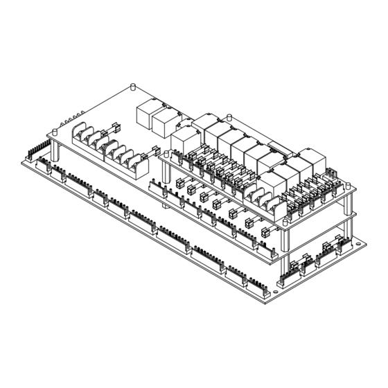
- Page 2 PLCCOMP or XPLCCOMP or both PLC compilers can be used with the RTK3, just like the PLCIO2. The RTK3 also retains the Fast I/O feature, which is now dedicated to a sourcing sensor input and relay output. There are three layers in the RTK3 to minimize footprint and maximize cabinet efficiency. Only rarely used connectors are located on the backside of the unit to allow mounting against the cabinet wall if necessary.
- Page 3 RTK3 Servo Drive Note the simplified layout and wiring enabled by the RTK3. Fewer individual wires (thin lines) are used and intermediate terminal block connections are reduced. Cables (thick lines) with quick connect ends replace many individual wires. Integrated components and specialized connection points on the RTK3 reduce the quantity of external hardware required.
-
Page 4: Power Connection
Limit switch wiring should be done from the “X- / X+ / Y- / Y+ LIMITS” and “W+ / W- / 5+ / 5- LIMITS” headers. When using a Centroid DC brushed servo drive with an RTK3, the “G”... -
Page 5: Output Wiring
Each power relay output is protected by a fuse. The “DOOR FAN” and “CONSOLE” unswitched 110VAC outputs are also fuse protected. Fuses are 5x20mm and should be rated equal to or less than the ratings printed on the RTK3 for safety. Signal relays, such as those on the inverter outputs, are not fuse protected. -
Page 6: Configurable Outputs
Outputs 11 and 37 may be configured as 24VAC or relay contact outputs. These outputs are routed to the “AUX 2 / CHILLER” connector. The configurable output jumper settings must be verified before connecting these outputs to prevent damage to the RTK3 or associated hardware. Internal Circuitry... - Page 7 The analog output has a 12-bit resolution and can be configured for 0 to +5VDC or 0 to +10VDC output. The analog ground should not be connected to other grounds on the RTK3. All input and output functions required for a standard inverter connection are located on the 15 pin “INVERTER” connector.
-
Page 8: Analog Output Adjustment
Pin 1 Emergency Stop Connector The E-stop connector has an input and output, unlike most RTK3 connectors. The input notifies the control of an external E-stop press. The output allows an E-stop to be triggered by the PLC program. Because the E-stop connector sources 24VAC, a 24VAC contactor coil must be used. -
Page 9: Status Indicator Leds
When output 40 is off, output 31 and input 26 work normally. In the RTK3 implementation of the Fast I/O, input 26 is dedicated to a sourcing tool counter sensor and output 31 controls the carousel enable relay. Output 40 is not a physical output, since using this output for purposes other than Fast I/O enable could cause confusion. - Page 10 Range 2 / Arm Stop Sinking Bottom AUX SPINDLE INPUTS Range 1 / Arm Home Sinking Bottom AUX SPINDLE INPUTS Spindle Chiller OK Sinking Bottom AUX SPINDLE INPUTS * Fast I/O Related 10 of 16 svn://software/hardware/RTK3/docs/rtk3_man.doc MRR 6/24/08 9:03 AM...
-
Page 11: Output Map
Bottom AUX DRIVERS 2 Auxiliary 15 Open Collector Bottom AUX DRIVERS 2 Auxiliary 16 Open Collector Bottom AUX DRIVERS 2 * Fast I/O Related ^ Often used to store the tool number 11 of 16 svn://software/hardware/RTK3/docs/rtk3_man.doc MRR 6/24/08 9:03 AM... - Page 12 RTK3 Specifications Characteristic Min. Typ. Max. Unit 5 Volt Supply Current 24 Volt Supply Current Input Pullup Voltage Input On Voltage Input Off Voltage 1.25 Power Relay Output Current 0.01 A @ 250VAC Power Relay Output Current 0.01 A @ 30VDC...
- Page 13 RTK3 Mounting Dimensions 4.275 12.000 11.800 5.450 5.275 0.200 0.475 0.200 0.500 4.375 5.000 13 of 16 svn://software/hardware/RTK3/docs/rtk3_man.doc MRR 6/24/08 9:03 AM...
- Page 14 Analog Offset Pot Air Low Input 24 Ground 24 VDC Pin 1 Chassis Ground Analog Gain Pot Door Interlock Input 24 Ground Inverter Output Configuration Jumpers 24 VDC Pin 1 Chassis Ground 14 of 16 svn://software/hardware/RTK3/docs/rtk3_man.doc MRR 6/24/08 9:03 AM...
- Page 15 Spindle Fan 220 AC2 Pin 1 Chassis Ground 220 AC1 Input 220 AC2 Input Pin 1 Chassis Ground Flood Output Flood Common 24 AC2 Carousel Direction 1 Carousel Direction 2 Carousel Common 24 AC2 15 of 16 svn://software/hardware/RTK3/docs/rtk3_man.doc MRR 6/24/08 9:03 AM...
- Page 16 110 ACN Chassis Ground Pin 1 Red Light Output 110 ACN Chassis Ground Pin 1 Green Light Output 110 ACN Chassis Ground Pin 1 Yellow Light Output 110 ACN Chassis Ground Pin 1 16 of 16 svn://software/hardware/RTK3/docs/rtk3_man.doc MRR 6/24/08 9:03 AM...
Need help?
Do you have a question about the RTK3 and is the answer not in the manual?
Questions and answers