Table of Contents
Advertisement
Centroid M-Series Operators Manual
CNC Software version: CNC11 V.3.14
Models: M400 & M39
www.centroidcnc.com
v3.14_CENTROID_mill_operators_manual.pdf 4-9-2015 Copyright © 2013-2015 CENTROID
U.S. Patent #6490500
M400 & M39
Operators Manual
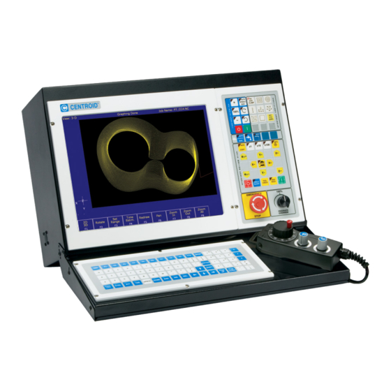
Operators Panel
Intercon Conversational Programming
CNC Program codes
M code functions
CNC Software Messages
1-1
Introduction
2-1
Main Screen
3-1
4-1
Part Setup
5-1
Tool Setup
6-1
Running a Job
7-1
Utility Menu
Digitizing
8-1
9-1
Probing
10-1
11-1
12-1
G- Codes
13-1
Configuration
14-1
15-1
Advertisement
Table of Contents


Need help?
Do you have a question about the M400 and is the answer not in the manual?
Questions and answers