
Related Manuals for Di-soric PS-30


Summary of Contents for Di-soric PS-30
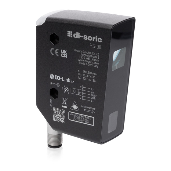
- Page 1 2D LASER PROFILE SENSOR PS-30 600015-0000EN · Rev 1 · 2022/03 OPERATING INSTRUCTIONS...
-
Page 2: Table Of Contents
PS-30 CONTENTS 1 PRELIMINARY NOTE 1.1 Symbols used ................................4 1.2 Warning signs used ................................ 4 2 SAFETY INSTRUCTIONS 3 INTENDED USE 3.1 General description ................................ 6 3.1.1 Teach process and height profile ..........................7 3.1.2 Normal operation ..............................7 3.2 Interpretation of the similarity value .......................... - Page 3 PS-30 10 OPERATING MODES 10.1 Continuous mode ............................... 24 10.2 Triggered mode ................................24 11 PARAMETER SETTING 11.1 Parameter level basic functions ........................... 26 11.1.1 [Adjust threshold] ..............................26 11.1.2 [ROI marker] ............................... 26 11.1.3 [Profile properties] ............................... 26 11.1.4 [Profile manager] ..............................26 11.1.5 [Extended functions] ............................
-
Page 4: Preliminary Note
PS-30 1 PRELIMINARY NOTE Instructions, technical data, approvals and other information via QR code on the device / on the packaging or at www.di-soric.com. 1.1 SYMBOLS USED Prerequisites Handling instructions Reaction, result [...] Designation of keys, buttons or displays Cross-reference... -
Page 5: Safety Instructions
PS-30 2 SAFETY INSTRUCTIONS ƒ The device described is integrated as a subcomponent in one system. – The safety of this system is the responsibility of the manufacturer. – The system manufacturer is obligated to perform a risk assessment and use this to generate and include documentation regarding the legal and standard requirements for operators and users of the system. -
Page 6: Intended Use
PS-30 3 INTENDED USE 3.1 GENERAL DESCRIPTION The sensor projects a laser line on the object and determines the height profile of the object along the laser line using a triangulation process. The object to be detected must be in the operating range of the sensor for this to occur. -
Page 7: Teach Process And Height Profile
PS-30 3.1.1 TEACH PROCESS AND HEIGHT PROFILE The sensor is taught in the first work step (teach process). This process also applies the entire height profile determined by the laser line. The user then has the option to further limit the relevant profile range (ROI). -
Page 8: Interpretation Of The Similarity Value
PS-30 3.2 INTERPRETATION OF THE SIMILARITY VALUE The measured height profile (also called “profile” in the following) is compared internally with an active reference profile. The degree of similarity generates the internal measured value (matching value). The measured value determined by the sensor thus represents the degree of similarity of the measured profile to the activated reference profile. -
Page 9: Profile Properties
PS-30 Gz / Gx also directly defines: ƒ minimum object height to be detected reliably ƒ minimum object width to be detected reliably The height profiles are determined by the sensor with a higher resolution than Gz / Gx. Changes to the object height / width can thus be detected within the measurement uncertainty. -
Page 10: Function
ƒ Two profile ranges (ROIs), when activating the ROI marker, the two ROIs are displayed via two green marker pairs. ƒ Laser switch-off ƒ Profile heights ƒ Object offset in X / Z direction ƒ Statistical evaluations Further information www.di-soric.com Ò 213740 Ò Downloads Ò IODD 600015-0000EN · Rev 1 · 2022/03... -
Page 11: Installation
Mount the device so that the object to be detected is in the detection range of the sensor. u Use two M4 screws to secure the device for direct mounting. Additional accessories Ò www.di-soric.com Ò Accessories. 5.2 INSTALLATION INSTRUCTIONS 5.2.1 LATERAL INCLINATION... -
Page 12: Front Inclination
PS-30 5.2.2 FRONT INCLINATION Transmitter Receiver Interrupted laser line Fig. 5: Front inclination If the sensor inclination is from the front or rear, it must be ensured that the laser line reflected by the object can be detected by the receiver. -
Page 13: Preventing Multiple Reflections
PS-30 5.2.4 PREVENTING MULTIPLE REFLECTIONS Sensor Object Multiple reflections Fig. 6: Multiple reflections u Change the sensor position slightly, e.g. lateral or front inclination, reduce / increase spacing to object. 5.2.5 PREVENTING SOILING AND AMBIENT LIGHT Optical sensors should preferably be set up with the front panel downwards or parallel to the ground surface. -
Page 14: Electrical Connection
PS-30 6 ELECTRICAL CONNECTION The device may only be installed by a qualified electrician. u You must follow all national and international provisions regarding the setup of electro-technical systems. u Ensure a voltage supply according to EN 50178, SELV, PELV. PS30-05LL-500-500-IBS: cULus, Supply Class 2 u Disconnect the system from the mains. -
Page 15: Operating And Display Elements
PS-30 7 OPERATING AND DISPLAY ELEMENTS 1x LED yellow Switching state OUT1 1x LED green Lit LED = Power Graphic display Display of the measured matching value. Programming button [●] Selects parameters and confirms parameter values. Programming button [▲] Sets parameter values (scrolling by holding pressed, incrementally by pressing once). -
Page 16: Guided Teach / Teach Process For Reference Profiles
PS-30 8.1 GUIDED TEACH / TEACH PROCESS FOR REFERENCE PROFILES [Welcome, choose your language] [English] [Deutsch] [Français] [...] [Place object and [Save this object [Region of interest] [Back] [Back] [Back] [Position reference [Floating] [Fixed] [Back] [Save settings] [Adj. Threshold] [Back]... -
Page 17: Setting The Profile Range (Roi)
PS-30 w The sensor emits a red laser line with two vertical green ROI markers. u Position the sensor so that the laser line scans the area to be monitored and the object is within the operating range of 150 to 300 mm Ò “3.1 General description”, page 6. -
Page 18: Setting The Position Of The Reference Profile
PS-30 Red line in display: indicates the range determined from the laser line. White marker: indicates the fixed marker line. Green arrow marker: indicates the marker line to be moved. Two green projected vertical ROI markers on the laser line support setup. -
Page 19: Saving Reference Profiles
PS-30 Matching value > switching threshold (default = 90%), then the measured value appears in green → good part. Matching value < switching threshold (default = 90%), then the measured value appears in red → bad part. Natural fluctuations (noise, drift) are detected in the measured matching value. These measurement fluctuations mean that the matching value itself is normally <... -
Page 20: Finishing The Teaching Process
PS-30 8.1.7 FINISHING THE TEACHING PROCESS u [Select the next step] This step only appears if the selected memory space is available. w The options [Go to run mode] / [Add new profile] appear on the display. u Select with [▲] / [▼] and confirm with [●]. -
Page 21: Menu
PS-30 9 MENU 9.1 BASIC FUNCTIONS Guided Teach [Adj. threshold] [0...100%] [YES] [ROI Markings] [NO] Use Vision Assistant for optimization [Back] [Ext. Functions] [Back] 600015-0000EN · Rev 1 · 2022/03... -
Page 22: Extended Functions
PS-30 9.2 EXTENDED FUNCTIONS Guided Teach [Factory Reset] [YES] [NO] [Serial number Hardware version [Device Info] Software version FE Software version BE Software version COM Operating hours Start counter] [Display] [Back] 600015-0000EN · Rev 1 · 2022/03... - Page 23 PS-30 [CONT] [Configuration] [Trigger Mode] [TRIG] [HW] [Trigger source] [PDOUT] [no delay] [Output delay mode] [On impulse] [Trigger Delay] [0...5000 ms] [Integration Time] [AUTO...10] [High active] [Output Function] [Low active] [PNP] [Output Logic] [NPN] [local] / [PDOut] [Profile source select] [Back] 600015-0000EN · Rev 1 · 2022/03...
-
Page 24: Operating Modes
PS-30 [ON] [Display] [Brightness] [OFF] [G1ou], [r1ou] [Colour] [White], [Red], [Green] [Language] [EN, DE, FRA... [Back] 10 OPERATING MODES 10.1 CONTINUOUS MODE The “Continuous mode” is the factory setting. The sensor continually measures and compares the measured profiles, taking into account the switching threshold for the activated reference profile. - Page 25 PS-30 Fig. 10: Example – Triggering positive edge Trigger input Trigger signal 0: no action 1: Triggering on positive edge Switching output Readiness signal OUT2 0: Device busy, Output OUT1 invalid 1: Device ready for trigger signal, output OUT1 valid Switching output...
-
Page 26: Parameter Setting
PS-30 11 PARAMETER SETTING The device remains in operating mode during parameter setting. It continues to perform its monitoring functions with the existing parameters until the modification has been completed. The factory settings are listed at the end of these instructions Ò “11.2.1 [Factory setting]”, page 27 11.1 PARAMETER LEVEL BASIC FUNCTIONS... -
Page 27: Extended Functions]
PS-30 [Delete profile]: u Confirm the parameter with [●]. u Select the profile to be deleted with [▲ / ▼]. u Confirm the selection with [●] If the activated profile is to be deleted, a confirmation prompt will appear. If the activated profile is deleted, then a matching value can no longer be determined. Corresponding information regarding this appears on the display in Run mode. -
Page 28: Display]
PS-30 11.2.4 [DISPLAY] Display configuration u Confirm the parameter with [●]. w Display switches to the display settings. u Use [▲ / ▼] to select one of the following options. 1. [Brightness] 2. [Color] 3. [Language] 4. [Back] 11.2.5 [BACK] Finish parameter setting u Confirm the parameter with [ENTER]. -
Page 29: Trigger Delay]
PS-30 11.3.4 [TRIGGER DELAY] Setting the delay time for the trigger signal until the start measurement u Confirm the parameter with [●] and use [▲ / ▼] to select the value (0 - 5000 ms). u Confirm the selection with [●]. -
Page 30: Display] Submenu
PS-30 11.4 [DISPLAY] SUBMENU 11.4.1 [BRIGHTNESS] Setting the display brightness u Confirm parameter with [●] and use [▲ / ▼] to select one of the two options [ON] / [OFF]. u Confirm the selection with [●]. w The display brightness is applied. -
Page 31: Io-Link
11.5.2 DEVICE-SPECIFIC INFORMATION The IODDs required to configure the IO-Link device as well as detailed information about sensor values, diagnostic information and parameters can be found in an overview table at www.di-soric.com. 11.5.3 PARAMETER SETTING TOOLS All required information regarding the required IO-Link hardware and software can be found at www.di-soric.com Ò... -
Page 32: Troubleshooting
PS-30 12 TROUBLESHOOTING 12.1 ERROR MESSAGES ON THE DISPLAY Display Possible cause Solution Profile X Sensor is in normal operation. There is no fault. No action required Object out of range Object is located outside (too far / too close) of Increase / Decrease distance to object. -
Page 33: Maintenance, Repairs, Disposal
PS-30 13 MAINTENANCE, REPAIRS, DISPOSAL Defective sensors may only be repaired by the manufacturer. u Keep the front panel of the device free of soiling. u The device should be disposed after use in an environmentally-friendly manner according to any valid national regulations. - Page 34 SOLUTIONS. SOLUTIONS. CLEVER. PRACTICAL. CLEVER. PRACTICAL. di-soric GmbH & Co. KG | Steinbeisstrasse 6 | 73660 Urbach | Germany Phone +49 71 81 98 79-0 | Fax +49 71 81 98 79-179 | info @ di-soric.com www.di-soric.com...
Need help?
Do you have a question about the PS-30 and is the answer not in the manual?
Questions and answers