Table of Contents
Advertisement
Quick Links
WLD3393
WLD3343 Laser Diode Driver
Evaluation Board
GENERAL DESCRIPTION:
Use the WLD3393 Evaluation Board to rapidly
prototype a complete laser diode control system
using the cutting edge technology of the
WLD3343 Laser Diode Driver.
switches, connectors, and trimpots make
confi guration and operation simple. Input and
output cables are also included.
Operate in either constant current (CC) or
constant power (CP) mode.
12-turn trimpot allows fi ne adjustment of laser
diode forward current (CC Mode) or monitor
photodiode current (CP Mode). Another trimpot
sets the laser diode forward current limit. The
input cable allows easy connection to your
power supply and monitoring equipment while
the output cable quickly connects to your laser
diode and monitor photodiode.
High power applications can use the onboard
fan connector to power a WXC303 or WXC304
(+5 VDC or +12 VDC) fan attached to a
WHS302 heatsink.
The prior revision of the board was black. Click
http://www.teamwavelength.com/downloads/
datasheets/wld3393b.pdf
that revision.
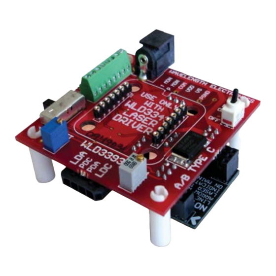
Figure 1: Top View
Optional
Supply Input
Fan
Power
WLD 3393
Sockets
Mode
Switch
© 2013
Onboard
An onboard
for the datasheet for
Input Cable
Connector
WAVELENGTH ELECTRONICS
FAN
(+)
(-)
USE
IMON
PMON
1
WITH
SET
WLD3343
2.5
PDM
LASER
COM
DRIVER
CC
ONLY
CP
SET
WLD3393
LIM
Output Cable Connector
WLD3393-00400-K
WLD3343 NOT INCLUDED
FEATURES:
• Operates all Laser Diode Pin Confi gurations
• Two Confi gurable Output Current Ranges
(200 mA or 2.0 Amps)
• Constant Current or Constant Power Operation
• Onboard Current Setpoint Trimpot
• Adjustable Current Limit
• Enable/Disable Switch and LED
• Includes Input/Output Cable Set
• Includes a Fan Connection
• Easily Connects to an External Control
Potentiometer or Voltage Source
• Includes 2.5 mm jack input for use with
PWRPAK power supplies
Ordering Information
WLD3393
2 A Evaluation Board for WLD3343
WLD3343
2.2 A Laser Diode Driver
WLD3343HB
2.2 A Li+ Battery-Compatible Driver
WLD3343-2L
2.2 A Lower Noise Laser Diode Driver
WLD3343-3A
3 A Laser Diode Driver
3 A Lower Noise Laser Diode Driver
WLD3343-3L
5 V Power Supply
PWRPAK-5V
PWRPAK-7V
7 V Power Supply
PWRPAK-9V
9 V Power Supply
Output Current
Enable/Disable
Switch
ENABLE
0N
OFF
Index Marker
Laser Diode
Configuration
NOTE:
LINE UP
Board
ARROW WITH
LASER TYPE
INDICATED ON
MAIN BOARD
January, 2013
e
Pb
RoHS
www.teamWavelength.com
Advertisement
Table of Contents

Related Manuals for Wavelength Electronics WLD3393


Summary of Contents for Wavelength Electronics WLD3393
- Page 1 WLD3343 Laser Diode Driver Evaluation Board WLD3343 NOT INCLUDED GENERAL DESCRIPTION: RoHS Use the WLD3393 Evaluation Board to rapidly FEATURES: prototype a complete laser diode control system • Operates all Laser Diode Pin Confi gurations using the cutting edge technology of the •...
- Page 2 PAGE 2 Figure 2: WLD3393 Schematic © 2013 WLD3393-00400-K www.teamWavelength.com...
-
Page 3: Electrical And Operating Specifications
12 mA. This specifi cation applies to Rev. E forward. Noise: To further reduce noise, the WLD3343-2L and WLD3343-3L models are available. Both are about 2.5 times lower noise than the WLD3343 and WLD3343-3A, respectively. Constant Power (CP) mode is not available in these models. © 2013 WLD3393-00400-K www.teamWavelength.com... -
Page 4: Test Conditions
Thermal Washer and 3.5 CFM fan Solder temp @260˚C Seconds Pin Solderability POWER SUPPLY 5-12 Voltage, V Volts Current, V supply, quiescent MONITOR ACCURACY Monitor Voltage versus Expected Output Current, based on transfer function PD Monitor versus Actual Setpoint versus Actual © 2013 WLD3393-00400-K www.teamWavelength.com... - Page 5 Refer to the chart shown below and note that the Load Line is in the Unsafe Operating Areas for use with no heatsink (1) or the heatsink alone (2), but is outside of the Unsafe Operating Area for use with heatsink and Fan (3). Graphs assume: 25°C Ambient 75°C Case © 2013 WLD3393-00400-K www.teamWavelength.com...
- Page 6 Match up the notch in the WLD3343 with the index marker shown in Figure 3. Align the WLD3343 pins with the WLD3393 sockets ensuring that all pins are lined up. Press fi rmly to seat the WLD3343. Make sure that none of the pins of the WLD3343 were bent during insertion before continuing.
- Page 7 WLD3393 for constant power mode (see Figure 1). Set the PD RANGE jumper on the bottom of the WLD3393 to either the 200 A or the 2 mA range, depending on the specifi cations of your photodiode. See Figure 4 for the location of the PD Current Range jumper.
- Page 8 To confi gure the WLD3393 for your laser diode type, connect the confi guration board to the bottom of the WLD3393 so that the arrow on the protruding edge of the confi guration board points to either A/B or C. Refer to Figure 6 for example installation.
- Page 9 Power Select Jumper. See Step 3 for location. Use PGND for the power return. The common (COM) terminal on the WLD3393 is not intended to act as a power connection, but as the low noise ground reference for connecting an external VSET source, and for monitoring the IMON, PMON, and PDM signals.
- Page 10 STEP 7: SET THE LASER DIODE CURRENT LIMIT The WLD3393 LIM trimpot adjusts the laser diode current limit from zero to the full 200 mA or 2.2 A, depending on the laser diode current range selected. For accurate laser diode current limit confi guration follow these steps sequentially: 1.
- Page 11 * 1.2 [ AMPS ] IMON IMON Table 4: Convert PMON or PDM Voltage to Photodiode Current 200 μA Range 2 mA Range PDI = V 100 [ μ A ] PDI = V [ mA ] PMON * PMON © 2013 WLD3393-00400-K www.teamWavelength.com...
- Page 12 0 to 2.5 V. To use only the onboard SET trimpot, place the VSET SOURCE jumper on the bottom of the WLD3393 evaluation board in the “T” position, and do not connect an external voltage source to the SET terminal on the terminal block.
-
Page 13: Application Notes
170 mA (200 mA range) or 1.7 A (2 A range). Bandwidth Optimization To improve bandwidth, shorten the cables. Expect 1.8 MHz at 200 mA and 850 kHz at 2 A (sine wave 3 dB point), with factory length cables. © 2013 WLD3393-00400-K www.teamWavelength.com... -
Page 14: Mechanical Specifications
0.93 [23.6] 1.00 [25.4] 0.56 [14.2] The WLD3343 connects to the evaluation board by two 7-pin SIP sockets. The socket manufacturer is Aries Electronics, PN 25-0513-10. Dimensions are shown in inches [mm]. All tolerances are ±5%. © 2013 WLD3393-00400-K www.teamWavelength.com... -
Page 15: Certification And Warranty
WARRANTY SERVICE: LIFE SUPPORT POLICY: For warranty service or repair, this product must As a general policy, Wavelength Electronics, Inc. be returned to the factory. An RMA is required does not recommend the use of any of its products for products returned to Wavelength for warranty in life support applications where the failure or service.
Need help?
Do you have a question about the WLD3393 and is the answer not in the manual?
Questions and answers