Wavelength Electronics WLD3393 Manual
Demo board for the wld3343
Hide thumbs
Also See for WLD3393:
- Datasheet and operating manual (28 pages) ,
- Quick start manual (15 pages)
Advertisement
Quick Links
WLD3393 Rev B
WLD3343 Laser Diode Driver
Demo Board
GENERAL DESCRIPTION:
Use the WLD3393 Demo Board to rapidly
prototype a complete laser diode control system
using the cutting edge technology of the
WLD3343
Laser Diode Driver.
switches, connectors, and trimpots make
confi guration and operation simple. Input and
output cables are also included.
Operate in either constant current (CC) or
constant power (CP) mode.
12-turn trimpot allows fi ne adjustment of laser
diode forward current (CC Mode) or monitor
photodiode current (CP Mode). Another trimpot
sets the laser diode forward current limit. The
input cable allows easy connection to your
power supply and monitoring equipment while
the output cable quickly connects to your laser
diode and monitor photodiode.
High power applications can use the onboard
fan connector to power a WXC303 or WXC304
(+5 VDC or +12 VDC) fan attached to a WHS302
heatsink.
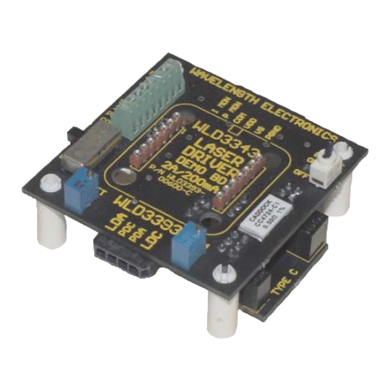
Figure 1: Top View
Fan
Terminals
WLD 3393
Sockets
Mode
Switch
© 2001, 2003, 2009
Onboard
An onboard
Input Cable Connector
WAVELENGTH
ELECTRONICS
FAN
(+)
(-)
IMON
PMON
1
SET
USE
2.5
PDM
WITH
COM
WLD3343
ONLY
CC
CP
WLD3393
SET
LIM
Output Cable Connector
WLD3393-00400-A Rev F
WLD3343 NOT INCLUDED
FEATURES:
• Operates all Laser Diode Pin Confi gurations
• Two Confi gurable Output Current Ranges
(200 mA or 2.0 Amps)
• Constant Current or Constant Power Operation
• Onboard Current Setpoint Trimpot
• Adjustable Current Limit
• Enable/Disable Switch and LED
• Includes Input/Output Cable Set
• Includes a Fan Connector
• Easily Connects to an External Control
Potentiometer or Voltage Source
Output Current
Enable/Disable
ENABLE
Switch
0N
OFF
Index Marker
NOTE
LINE UP
ARROW W/
LASER TYPE
INDICATED
ON MAIN BD
August, 2009
Pb
RoHS
Laser Diode
Configuration
Board
www.teamwavelength.com
Advertisement

Related Manuals for Wavelength Electronics WLD3393


Summary of Contents for Wavelength Electronics WLD3393
- Page 1 WLD3343 NOT INCLUDED WLD3393 Rev B WLD3343 Laser Diode Driver Demo Board GENERAL DESCRIPTION: Use the WLD3393 Demo Board to rapidly prototype a complete laser diode control system using the cutting edge technology of the WLD3343 Laser Diode Driver. Onboard...
- Page 2 PAGE 2 Figure 2: WLD3393 Schematic WLD3393-00100-C10 SIZE DWG (PRR) NO. © 2001, 2003, 2009 WLD3393-00400-A Rev F www.teamwavelength.com...
-
Page 3: Setup Information
Match up the notch in the WLD3343 with the index marker shown in Figure 3. Align the WLD3343 pins with the WLD3393 sockets ensuring that all pins are lined up. Press fi rmly to seat the WLD3343. Make sure that none of the pins of the WLD3343 were bent during insertion before continuing. - Page 4 Monitor the voltage at the PDM pin on the terminal block on the top side of the WLD3393. Before powering the unit on to operate in constant current mode, make sure that the mode switch is in the CC position (see Figure 1). Select the output current range by setting the LD RANGE jumper on the back of the WLD3393 to either the 200mA or the 2A position.
- Page 5 To confi gure the WLD3393 for your laser diode type, connect the confi guration board to the bottom of the WLD3393 so that the arrow on the protruding edge of the confi guration board points to either A/B or C. Refer to Figure 6 for example installation.
- Page 6 Use PGND for the power return. The common (COM) terminal on the WLD3393 is not intended to act as a power connection, but as the low noise ground reference for connecting an external VSET source, and for monitoring the IMON, PMON, and PDM signals.
- Page 7 STEP 6: SET THE LASER DIODE CURRENT LIMIT The WLD3393 LIM trimpot adjusts the laser diode current limit from zero to the full 200 mA or 2.0 Amps, depending on the laser diode current range selected. For accurate laser diode current limit confi...
- Page 8 Table 4: Convert PMON or PDM voltage to Photodiode Current 200 µA Range 2 mA Range PDI = V 100 [ µ A ] PDI = V [ mA ] PMON * PMON © 2001, 2003, 2009 WLD3393-00400-A Rev F www.teamwavelength.com...
- Page 9 SET terminal on the terminal block on the top side of the WLD3393 evaluation board. When the SET SOURCE jumper is in the “X” position, the voltage dialed in using the SET trimpot on the WLD3393 is ignored. Figure 6 shows the jumper location.
-
Page 10: Mechanical Specifications
PAGE 10 TOP VIEW (inches) WAVELENGTH ELECTRONICS ENABLE IMON PMON 2.07 WITH WLD3343 1.08 2.25 ONLY 1.60 WLD3393 0.65 0.41 0.19 0.19 0.65 1.60 2.07 2.25 RIGHT SIDE VIEW 0.48 0.68 1.16 © 2001, 2003, 2009 WLD3393-00400-A Rev F www.teamwavelength.com... -
Page 11: Warranty
LIFE SUPPORT POLICY: WARRANTY SERVICE: As a general policy, Wavelength Electronics, Inc. For warranty service or repair, this product must does not recommend the use of any of its products be returned to the factory. An RMA is required...
Need help?
Do you have a question about the WLD3393 and is the answer not in the manual?
Questions and answers