Table of Contents
Advertisement
Quick Links
DATASHEET AND OPERATING GUIDE
WTC32ND & WTC32ND-EV
Ultrastable TEC Controller & Evaluation Board
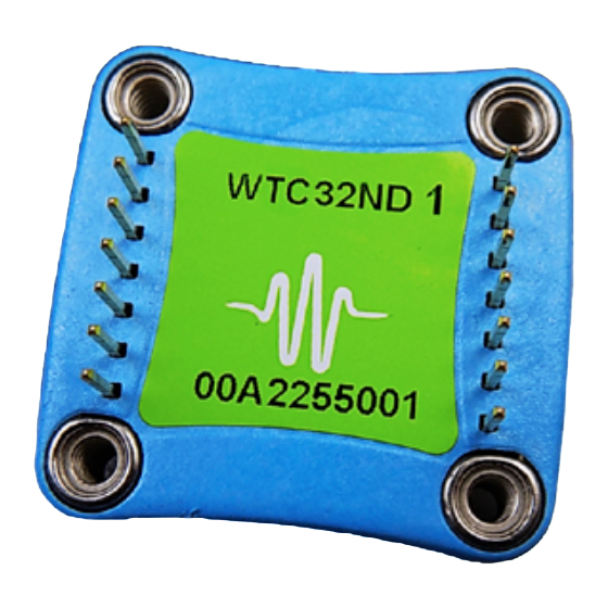
WTC32ND
NEW IMAGE COMING
NEW IMAGE COMING
PRECISION, STABILITY & VERSATILITY
The WTC32ND is a compact, analog PI (Proportional,
Integral) control loop circuit optimized for use in ultrastable
thermoelectric temperature control applications. It easily
handles variable operating conditions with a stability of better
than 0.0009ºC. The temperature setpoint is set by a remote
voltage signal. It is capable of controlling both thermoelectric
and resistive heaters, and only five external resistors are
needed to optimize the controller for your specific application.
The WTC32ND-EV Evaluation Board is available to quickly
integrate the WTC32ND into your system and can be
optimized for sensor type. Use the adjustable trimpots to
configure heat and cool current limits, proportional gain, and
integrator time constant.
CONTENTS
SOON
SOON
WTC32ND-EV
PAGE
2
4
5
6
8
11
12
20
28
32
34
36
37
FEATURES AND BENEFITS
• Linear PI Control Stability of 0.0009°C
• Heat and Cool Current Limits
• Adjustable Sensor Bias Current
• Drive ±2.2 A of TEC or Resistive Heater Current
• Small Size of 1.3" X 1.28" X 0.313"
• Supports Thermistors, RTDs, and IC Sensors
• Single Supply Operation: +5 V to +30 V
• 14-pin DIP PCB Mount
• Monitor Actual Temperature
• Quickly and easily integrated with WTC32ND-EV
Evaluation Board
BUILT-IN SAFETY
To protect the device, heat and cool limits can be set
independently. This safety feature guarantees that your
thermoelectric cooler will never be driven beyond your
specified limits.
LEADING EDGE APPLICATIONS
The robust and reliable WTC32ND has been designed
into electro-optical systems, airborne instrumentation,
spectroscopic
monitors,
equipment. It is particularly well-suited to applications
where temperature is scanned across ambient.
ORDERING INFORMATION
PART NO
DESCRIPTION
WTC32ND
±2.2 A Temperature Controller
±2.2 A Li-Ion Battery-Compatible
WTC32ND-HB
Temperature Controller
Evaluation Board for WTC32ND
WTC32ND-EV
Temperature Controller
WEV300
Thermal Management Kit, no fan
WEV301
Thermal Management Kit, 5 V fan
WEV302
Thermal Management Kit, 12 V fan
e
Pb
RoHS
and
medical
diagnostic
Advertisement
Table of Contents

Related Manuals for Wavelength Electronics WTC32ND


Summary of Contents for Wavelength Electronics WTC32ND
-
Page 1: Table Of Contents
WTC32ND into your system and can be equipment. It is particularly well-suited to applications optimized for sensor type. Use the adjustable trimpots to where temperature is scanned across ambient. configure heat and cool current limits, proportional gain, and integrator time constant. -
Page 2: Quick Connect Guide
Pin 1 on the WTC32ND. To ensure safe operation of the WTC32ND Thermoelectric Controller, it is imperative Figure 2 is the top view of the WTC32ND-EV, illustrating the that you determine that the unit will be onboard switches, trimpots, and connectors. - Page 3 Control Loop TOP VIEW Actual Temperature Monitor voltage TIE GROUND CONNECTIONS DIRECTLY TO PIN 13 Figure 3. WTC32ND Quick Connect for TEC with Thermistor QUICK CONNECT LEGEND FUNCTION WTC32ND & EVAL BOARD WTC32ND ALONE Table 6 on page 17 Limits Adjust LIMA &...
-
Page 4: Wtc32Nd-Ev Evaluation Board Schematic
WTC32ND TEMPERATURE CONTROLLER WTC32ND-EV EVALUATION BOARD SCHEMATIC © 2022 www.teamWavelength.com... -
Page 5: Pin Descriptions - Wtc32Nd
Ground. Connect the power supply ground connections to GND (Pin 13). All ground connections to this pin should be wired separately. Power Drive Supply Input. Provides power to the WTC32ND H-Bridge power stage. Supply range input for this pin is +3 to +30 Volts DC. The maximum current drain on this terminal should not exceed 2.2 A. -
Page 6: Pin Descriptions - Wtc32Nd-Ev Eval Board
Test Point 7 I TERM (measure resistance across TP6 and TP7) Terminal Block 1 (TB1), Input Power Terminal Block Power supply input for control electronics. Directly connected to WTC32ND V Voltage Supply (Pin 1). NOTE: Use either Input Supply (P1) or V on TB1 but not both. - Page 7 WTC32ND TEMPERATURE CONTROLLER Table 3. Control and Monitor Transfer Functions FUNCTION WTC32ND WTC32ND-HB WTC32ND-EV DESCRIPTION The controller drives the TEC or heater to RSET to Sensor Voltage 1 V / V make the voltage across the sensor match the RSET voltage.
-
Page 8: Electrical Specifications - Wtc32Nd
WTC32ND TEMPERATURE CONTROLLER ELECTRICAL SPECIFICATIONS — WTC32ND ABSOLUTE MAXIMUM RATINGS SYMBOL WTC32ND WTC32ND-HB UNIT NOTE Voltage on Pin 1 Supply Voltage 1 +4.5 to +30 +3 to +5.5 Volts DC Can be connected to V Consult SOA Calculator Voltage on Pin 14... - Page 9 WTC32ND TEMPERATURE CONTROLLER PARAMETER SYMBOL WTC32ND WTC32ND-HB UNIT NOTE VSET Input Impedence VSET MΩ VSET Damage Threshold VSET > V + 0.7 or < -0.7 Volts TSET = 25ºC using 10 kΩ Setpoint vs. Actual T Accuracy <2 thermistor BIAS CURRENT...
- Page 10 WTC32ND TEMPERATURE CONTROLLER ELECTRICAL SPECIFICATIONS — WTC32ND-EV + WTC32ND PARAMETER SYMBOL WTC32ND-EV UNIT POWER SUPPLY = +4.5 to +30 Enable LED will not turn on Power Supply Voltage Volts = +3 to +30 when less than 3.5 V Quiescent Current DD-QUIESCENT = 10.5...
-
Page 11: Safety Info & Thermal Considerations
WTC32ND TEMPERATURE CONTROLLER SAFETY INFORMATION THEORY OF OPERATION & THERMAL DESIGN The WTC32ND is a linear temperature controller that delivers bidirectional current to Peltier Effect thermoelectric coolers CONSIDERATIONS (TEC), or unidirectional current to resistive heaters. SAFE OPERATING AREA — DO NOT EXCEED... -
Page 12: Operating Instructions - Wtc32Nd + Eval
8 mA of current. If a fan is needed, the fan draw current on V will also need to be added to the minimum required current. powers the WTC32ND output stage and must be sufficient to provide 1.1 times quiescent current and TEC current. = 1.1 * (I S_QUIESCENT... - Page 13 Data Acquisition Failsafe Protection circuit. NOTE: When the VSET SOURCE jumper is in the “X” position or removed, the voltage dialed in using the SET T trimpot on the WTC32ND-EV is ignored. Trimpot is Source RSET is Source HSET is Source (Factory Default) Figure 7.
- Page 14 Or use Equation 1 to calculate the P GAIN trimpot Proportional Gain (P GAIN) and Integrator Time Constant resistance. (I TERM) can be adjusted during operation, but resistance readings will not match the table if the WTC32ND is installed. Equation 1. Calculating R from P GAIN 100,000 [Ω]...
- Page 15 Where: is in Ohms (Ω) is in seconds 1. Match up the notch on the WTC32ND with the silkscreen on the PCB. 2. Align the pins with the sockets, ensuring that all pins are lined up in their respective sockets.
- Page 16 ATTACH THE HEATSINK & FAN If a fan is required, align the fan with the heatsink. The direction The WTC32ND is designed to handle currents as high of air flow, as indicated on the fan, is into the heatsink. as 2.2 A and installing a heatsink and fan is optional when using less than +5 V or 500 mA during operation.
- Page 17 Use PGND for the power return. The common (COM) Once the LIMA and LIMB values are determined, toggle terminal on the WTC32ND-EV is not intended to act as a the ENABLE to ON to apply power to V and V...
- Page 18 SEN+ and SEN- on Terminal Block 4 (TB4). ONLY Connect LM335 and AD590, which are polarized, as shown below. SEN+ Figure 15. WTC32ND-EV Evaluation Board & Voltmeter SEN+ To read the ACT T, attach the voltmeter to the ACT T and SEN- 10 kΩ...
- Page 19 WTC32ND TEMPERATURE CONTROLLER ADJUST THE TEMPERATURE SETPOINT VOLTAGE The setpoint voltage can be adjusted either by using the evaluation board’s onboard SET T trimpot or by connecting a remote voltage source or potentiometer to the RSET or HSET inputs. Only one of these setpoints can be used.
-
Page 20: Design Guide - Wtc32Nd
SAFE OPERATING AREA AND THERMAL DESIGN CONSIDERATIONS SOA charts are included in this datasheet for quick reference, but we recommend you use the online tools instead. Refer to the SOA calculator for the WTC32ND. www.teamwavelength.com/support/design-tools/soa-tc-calculator/ ENSURE SAFE OPERATION... - Page 21 Table 11 on page 27 Table 12 on page 27 The diagrams on this page demonstrate how to configure the WTC32ND Table 10 on page 26 for operation with a thermistor temperature sensor. An online calculation Equation 6 &...
- Page 22 Table 11 on page 27 Table 12 on page 27 The diagrams on this page demonstrate how to configure the WTC32ND for Table 10 on page 26 operation with a Platinum RTD temperature sensor. An online calculation Equation 6 &...
- Page 23 Table 11 on page 27 Table 12 on page 27 The following diagrams demonstrate how to configure the WTC32ND for Table 10 on page 26 operation with a National Semiconductor LM335 temperature sensor. An Equation 7...
- Page 24 V be +8 V or greater. Table 9 on page 25 LIMA The following diagrams demonstrate how to configure the WTC32ND for Table 9 on page 25 LIMB operation with an Analog Devices AD590 Temperature Sensor. An online...
- Page 25 WTC32ND TEMPERATURE CONTROLLER Figure 25 shows fixed heating and cooling limits and is the CHOOSE THE HEATING AND COOLING standard implementation. CURRENT LIMIT RESISTORS — R & R Use Table 9 to select appropriate resistor values for R . The Heat and Cool Current Limits graph, Figure 24, shows the range of error for Table 9.
- Page 26 RESISTIVE HEATER TEMPERATURE CONTROL SET THE SENSOR BIAS CURRENT AND SENSOR GAIN RESISTORS The WTC32ND can operate resistive heaters by disabling the cooling output current. When using Resistive Heaters Table 10 lists the suggested resistor values for R and R...
- Page 27 WTC32ND TEMPERATURE CONTROLLER SET THE CONTROL LOOP PROPORTIONAL SET THE CONTROL LOOP INTEGRATOR TIME GAIN RESISTOR CONSTANT The control loop Proportional Gain can be set by inserting a To set the control loop Integrator Time Constant (I ), insert resistor, R...
-
Page 28: Additional Technical Notes
WTC32ND TEMPERATURE CONTROLLER ADDITIONAL TECHNICAL NOTES DAQ PROTECTION -- CHANGE DEFAULTS If the voltage set by the external input drops below 0.3 V, This section includes useful technical information on these the failsafe circuit is triggered and the setpoint defaults to topics: 1 V. - Page 29 WTC32ND TEMPERATURE CONTROLLER ELIMINATING TRIMPOTS To simplify set up or to minimize thermal drift, Wavelength recommends that you eliminate trimpots in circuitry. The following details how to use fixed resistances in place of trimpots. Wavelength can load boards at the factory to your specific requirements.
- Page 30 WTC32ND TEMPERATURE CONTROLLER CHANGING LIM TO A FIXED VALUE CHANGING ONBOARD SETPOINT TRIMPOT TO A FIXED RESISTANCE • Connect an ohmmeter to TP1 & TP3, without the WTC32ND installed. • Connect an ohmmeter to TP1 & TP2, without the WTC32ND installed.
- Page 31 Do not exceed the Safe Operating Area (SOA). Exceeding the SOA voids the warranty. Refer to the Wavelength Electronics website for the most up-to-date SOA calculator for our products. The online tool is fast and easy to use, and also takes into consideration operating temperature.
-
Page 32: Troubleshooting
WTC32ND TEMPERATURE CONTROLLER TROUBLESHOOTING PROBLEM POTENTIAL CAUSES SOLUTIONS Temperature is decreasing The TEC may be connected The convention is that the red wire on the TEC module connects to when it should be backwards to the WTC TEC+ (Pin 12) and the black wire to TEC- (Pin 11). If your TEC is... - Page 33 Current limit may be set too low Increase the current limit but DO NOT exceed the specifications of the TEC or heater. The WTC32ND-EV is not The P GAIN or I TERM may Turn the P GAIN and I TERM trimpot screws clockwise to the setting...
-
Page 34: Mechanical Specifications
[22.86] 1.30 [33.0] PCB FOOTPRINT 0.945 [24.00] SQ. The WTC32ND can be directly soldered to a PCB or installed in a socket soldered to the PCB. Two 7-pin SIP sockets are required. Wavelength recommends 0.125 [3.18] Thru Sullins PPPC071LFBN-RC Socket. - Page 35 WTC32ND TEMPERATURE CONTROLLER MECHANICAL SPECIFICATIONS, continued 2.25 [57.15] 0.19 [4.83] 1.880 [47.75] 2.25 [57.15] 1.880 [47.75] Weights 1.6 oz WTC32ND-EV + WTC32ND 0.13[3.3] THRU WHS302 Heatsink 0.5 oz 0.19 [4.83] 4 PLS WXC303/4 Fan 0.3 oz 0.17 [4.32] 2.42 [61.47]...
-
Page 36: Cabling Specifications
WTC32ND TEMPERATURE CONTROLLER CABLING SPECIFICATIONS These cables are included with the WTC32ND-EV Evaluation Board. WTC3293-00101 INPUT CABLE PIN # COLOR FUNCTION MOLEX #43645-0600 BLUE PGND MICRO-FIT 6 CIRCUIT ORANGE SINGLE ROW RECPT BLACK WHITE GREEN WTC3293-00102 OUTPUT CABLE MOLEX #43645-0400... -
Page 37: Certification And Warranty
CERTIFICATION AND WARRANTY There are no user-serviceable parts inside this product. Return the CERTIFICATION product to Wavelength Electronics for service and repair to ensure that safety features are maintained. Wavelength Electronics, Inc. (Wavelength) certifies that this product met its published specifications at the time of shipment.
Need help?
Do you have a question about the WTC32ND and is the answer not in the manual?
Questions and answers