Table of Contents
Advertisement
Quick Links
Advertisement
Table of Contents

Related Manuals for Kuppersbusch ESW 308.6


Summary of Contents for Kuppersbusch ESW 308.6
- Page 1 KÜPPERSBUSCH CUSTOMER SERVICE Repair Manual ESW 308.6...
-
Page 2: Table Of Contents
Repair Manual VKS-H H1-58-01-02 ESW 308.6 Responsible: Rutz Tel.: (0209) 401-733 Fax: (0209) 401-743 Date: 17.10.1998 Contents Contents ..........2 Introduction and Safety Instructions . -
Page 3: Introduction And Safety Instructions
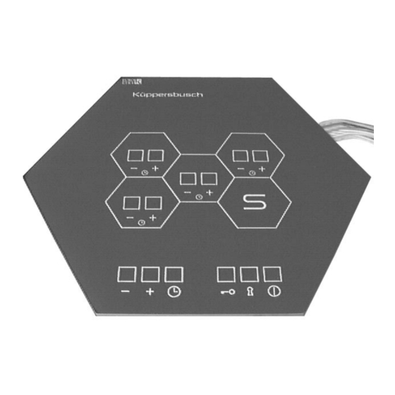
The control honeycomb ESW 308.6 is a sensor-controlled cooking honeycomb which allows controlling of the cooking zones without contacting them. In contrast to the forerunning model ESW 307.6, the ESW 308.6 is additionally equipped with a minute minder. From the outside, however, the functions have remained identical while the internal structure of the control electronics has completely changed. -
Page 4: Tools And Devices
Repair Manual VKS-H H1-58-01-02 ESW 308.6 2. Tools and Devices The following tools are required for a trouble-free performance of a customer service call: • • digital multimeter incl. measuring leads • • IC extraction tool for 28 poles • •... -
Page 5: Functional Description Of The Control Honeycomb
Repair Manual VKS-H H1-58-01-02 ESW 308.6 3. Functional Description of the Control Honeycomb See Operating and Installation Instructions ESW, valid: July 1997 Internal use only... -
Page 6: Components Of The Control Honeycomb
Newly supplied control honeycombs starting with the W-number xxxx will be equipped with the following combined power supply unit and power section: power section 2879 - rev. A electrical connection ESW 308.6 outside view of the lid ESW 308.6 power section mounted on lid Note: The power section may... -
Page 7: Control System
Repair Manual VKS-H H1-58-01-02 ESW 308.6 4.2 Control System The control board is connected to the power section by means of 2 cables. 1. a 4-pole cable for power supply 2. a 14-pole ribbon cable for power section control Internal use only... - Page 8 Repair Manual VKS-H H1-58-01-02 ESW 308.6 Before opening the appliance make sure to observe the safety instructions! In order to loosen the lid of the cabinet unscrew the 4 screws (marked with an ”X”). Internal use only...
-
Page 9: Disassembly Of The Power Section
Repair Manual VKS-H H1-58-01-02 ESW 308.6 4.3 Disassembly of the Power Section After the appliance has been DIS- CONNECTED FROM THE POWER SUPPLY and the heater cables have been removed, the 4 screws marked with an ”X” are removed (if required, the incoming cable must also be removed). -
Page 10: Disassembly Of The Control System
Repair Manual VKS-H H1-58-01-02 ESW 308.6 4.4 Disassembly of the Control System control board For the diassembly of the control board the steps ”Removing and loosening the lid with power section” have already been performed. Afterwards the 3 fastening screws of the control board are removed. -
Page 11: Adjustment And Balancing Of The Sensors
5. Adjustment and Balancing of the Sensors General For balancing the sensors of the ESW 308.6 it is no longer required to carry out manual adjustments via a potentiometer as with the forerunning model ESW 307.6. Sensor balancing of the ESW 308.6 is performed from the control field, i. -
Page 12: Main Reset
After approx. 2 minutes 4 successive acoustic signals will sound to signal that calibration is completed. In this status the ESW 308.6 can be operated as usual again. It is recommended, however, to check each sensor again. - Page 13 ”25”. When ”25” is reached, the sensor is still kept depressed until 4 successive acoustic signals sound. Now the values have been stored and the ESW 308.6 can be operated as usual.
-
Page 14: General Notes On Possible Faults
VKS-H H1-58-01-02 ESW 308.6 6. General Notes on Possible Faults The control honeycomb ESW 308.6 is not equipped with an optical fault display. Three defects may occur: 1. heater is defective 2. control board of the ESW 308.6 is defective 3. -
Page 15: Instructions For Replacing Glass Ceramic Honeycomb Units
H1-58-01-02 Instructions for replacing glass ceramic honeycomb units Replace the ceramic honeycomb as follows: Parts required: 53 69 25 Glass ceramic honeycomb 53 69 25 Casing section mechanism 53 69 30 Glass ceramic control honeycom 53 69 55 Casing section mechanism 09 15 81 Adhesive cleane 53 58 85... - Page 16 H1-58-01-02 Danger. Risk of accidents! Gloves and goggles must be worn! Cover the glass ceramic honeycomb to be replaced with a damp cloth and place a receptacle underneath to catch any glass splinters. Now using a controlled level of force break the glass and completely remove it.
- Page 17 H1-58-01-02 Fit the new glass ceramic honeycomb. Make sure the surfaces are level and the joints are of even thickness. Clean the glass ceramic honeycombs’s jointing surfaces with adhesive cleaner. Granite worktops should also be cleaned with adhesive cleaner. First coat worktops made from wood or chipboard with PACTAN primer and leave to dry.
Need help?
Do you have a question about the ESW 308.6 and is the answer not in the manual?
Questions and answers