Table of Contents
Advertisement
Quick Links
Advertisement
Table of Contents

Subscribe to Our Youtube Channel
Related Manuals for Kuppersbusch ESW 308.6


Summary of Contents for Kuppersbusch ESW 308.6
- Page 1 j}Ž‹}| j}ˆyŠ a†‹ŒŠ{Œ‡†‹ ]ko KHPFN...
- Page 2 Service Manual: H1-58-01-02-Ä Responsible: H. G. Streckert KÜPPERSBUSCH HAUSGERÄTE AG Email: georg.streckert@kueppersbusch.de Tel.: (0209) 401-724 Kundendienst Fax: (0209) 401-709 Postfach 100 132 Date: 29.04.2003 45801 Gelsenkirchen...
-
Page 3: Table Of Contents
The control unit at a glance ................... 5 Tools and Devices ......................5 Functional Description of the Honeycomb Control Unit..........6 Electronics of the ESW 308.6 ..................7 Universal electronics unit ..................7 Control System...................... 9 Disassembly of the Control Section ..............9 Adjustment and Balancing of the Sensors .............. -
Page 4: Introduction And Safety Instructions
The calibration procedure is dealt with in detail in a separate chapter. Furthermore, power supply unit and power section of the ESW 308.6 have been assembled on a joint printed-circuit board mounted on the lid. The connectors have also been changed. -
Page 5: The Control Unit At A Glance
H1-58-01-02-Ä The control unit at a glance 1. Glass ceramic-honeycomb control unit, layout 05 2. Housing - mechanical system 3. Circuit board flat, shallow Circuit board pointed 4. Screw M4 5. Power supply 6. Relay board 7. Housing - mechanical system 8. -
Page 6: Functional Description Of The Honeycomb Control Unit
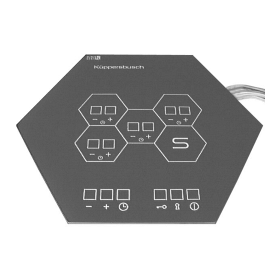
H1-58-01-02-Ä Functional Description of the Honeycomb Control Unit The honeycomb cooking zone is equipped with a convenient sensor control unit which is regulated by means of the control honeycomb. The markings in the honeycomb control unit repeat the layout of the cooking zones on the worktop. With the honeycomb control unit you can also control •... -
Page 7: Electronics Of The Esw 308.6
H1-58-01-02-Ä Electronics of the ESW 308.6 Universal electronics unit 5.1.1 Components The following spare parts are required when constructing a universal electronics unit: Spare part no. Quantity Indication 538414 Flat universal electronics unit 538415 Pointed universal electronics unit 538416 EEPROM... - Page 8 H1-58-01-02-Ä 5.1.2 Exchanging an universal electronics unit It is essential to observe the following on exchanging a universal electronics unit: Attention! It is essential to carry out a potential adjustment on the exposed conductive part prior to unpacking and installing the electronics unit! In the region of the elongated holes for attaching the universal honeycomb it must be ensured that the areas around the soldering joints are sufficiently covered with tape.
-
Page 9: Control System
H1-58-01-02-Ä Control System The control board is connected to the power section by means of 2 cables. 1. a 4-pole cable for power supply 2. a 14-pole ribbon cable for power section control. Disassembly of the Control Section Control board For the diassembly of the control board the steps "Removing and loosening the lid with power section"... - Page 10 H1-58-01-02-Ä Afterwards the 3 fastening screws of the control board are removed. The pc board is removed towards the top with the recess matching one of the fastening brackets. Then it is removed. The new control electronics is inserted and fastened by means of the 3 fastening screws.
-
Page 11: Adjustment And Balancing Of The Sensors
Adjustment and Balancing of the Sensors General For balancing the sensors of the ESW 308.6 it is no longer required to carry out manual adjustments via a potentiometer as with the forerunning model ESW 307.6. Sensor balancing of the ESW 308.6 is performed from the control field, i. - Page 12 When “25” is reached, the sensor is still kept depressed until 4 successive acoustic signals sound. Now the values have been stored and the ESW 308.6 can be operated as usual. Note: If more than 2 sensors have to be reset, automatic calibration has to be performed.
-
Page 13: Calibration Modus On Exchanging The Electronics Unit
After approx. 2 minutes (the electronics unit twice counts up to 60 seconds in the left segment indicator) 4 successive acoustic signals will sound to signal that calibration is completed. In this status the ESW 308.6 can be operated as usual again. It is recommended, however, to check each sensor again. -
Page 14: Faults
H1-58-01-02-Ä Faults General notes The control honeycomb ESW 308.6 is not equipped with an optical fault display. Three defects may occur: 1. heater is defective 2. control board of the ESW 308.6 is defective 3. power section of the ESW 308.6 is defective... -
Page 15: Rectifying Faults
H1-58-01-02-Ä Rectifying faults 7.2.1 The honeycomb is difficult to operate (The sensors react too sluggishly or not at all) Measure Erase the EEPROM modus and re-calibrate (see Manual). Replace the EEPROM should it not be possible to erase it or should it not be possible to carry out the process of removal. - Page 16 H1-58-01-02-Ä 7.2.3 Power supply for the relay platinum: consistent 15 volts at the connection Measure If one of the two voltages is not present or instable: Exchange the mains connection and/or, if necessary exchange the voltage regulator. 7.2.4 The honeycomb is difficult to operate (the sensors activate the wrong honeycombs or none at all) Measure Exchange the EPROM.
-
Page 17: Instructions For Replacing Glass Ceramic Honeycomb Units
H1-58-01-02-Ä Instructions for replacing glass ceramic honeycomb units Replace the ceramic honeycomb as follows: Parts required: 53 69 25 Glass ceramic honeycomb 53 69 25 Casing section mechanism 53 69 30 Glass ceramic control honeycomb 53 69 55 Casing section mechanism 09 15 81 Adhesive cleane 53 58 85... - Page 18 H1-58-01-02-Ä Danger. Risk of accidents! Gloves and goggles must be worn! Cover the glass ceramic honeycomb to be replaced with a damp cloth and place a receptacle underneath to catch any glass splinters. Now using a controlled level of force break the glass and completely remove it.
- Page 19 H1-58-01-02-Ä Fit the new glass ceramic honeycomb. Make sure the surfaces are level and the joints are of even thickness. Clean the glass ceramic honeycombs’s jointing surfaces with adhesive cleaner. Granite worktops should also be cleaned with adhesive cleaner. First coat worktops made from wood or chipboard with PACTAN primer and leave to dry.
Need help?
Do you have a question about the ESW 308.6 and is the answer not in the manual?
Questions and answers