Faulhaber MC 5004 Technical Manual
Hide thumbs
Also See for MC 5004:
- Communications manual (53 pages) ,
- Programming manual (20 pages) ,
- Communications manual (43 pages)
Table of Contents
Advertisement
Quick Links
Advertisement
Table of Contents
Troubleshooting

Related Manuals for Faulhaber MC 5004


Summary of Contents for Faulhaber MC 5004
- Page 1 Technical Manual MC 5004 WE CREATE MOTION...
- Page 2 Dr. Fritz Faulhaber GmbH & Co. KG. This document has been prepared with care. Dr. Fritz Faulhaber GmbH & Co. KG cannot accept any liability for any errors in this document or for the consequences of such errors. Equally, no liability can be accepted for direct or consequential damages resulting from improper use of the equipment.
-
Page 3: Table Of Contents
Content About this document ....................... 5 Validity of this document ..................5 Associated documents .................... 5 Using this document ....................5 List of abbreviations ....................6 Symbols and designations ..................7 Safety ..........................8 Intended use ......................8 Safety instructions ....................9 2.2.1 Dangers in the event of damages and changes ........ - Page 4 Content 4.3.4 Shielding ....................47 4.3.4.1 Establishing the shield connection ........48 4.3.4.2 Establishing shield connection with cable lug ..... 49 4.3.5 Sensor and encoder interfaces ............. 50 4.3.5.1 Analog sensors and analog Hall sensors ......51 4.3.5.2 Incremental encoders / Digital Hall sensors / Digital sensors 51 4.3.5.3 Encoders with absolute interface .........
-
Page 5: About This Document
About this document About this document Validity of this document This document describes the installation and use of the MC 5004 series. This document is intended for use by trained experts authorized to perform installation and electrical connection of the product. -
Page 6: List Of Abbreviations
About this document List of abbreviations Abbreviation Meaning Alternating Current Absolute encoder AGND Analog Ground AnIn Analog input Controller Area Network CAN_L CAN-Low CAN_H CAN-High Clock Clock with logically inverted signal Chip Select Chip Select Data Data cable Data Data cable with logically inverted signal DigIn Digital input DigOut... -
Page 7: Symbols And Designations
About this document Symbols and designations DANGER! Danger with high level of risk: if not avoided, death or serious injury will result. Measures for avoidance WARNING! Danger with medium level of risk: if not avoided, death or serious injury may result. ... -
Page 8: Safety
Safety Safety Intended use The Motion Controllers described here are designed for use as slaves for control and posi- tioning tasks for the following motors: DC-Micromotors Linear DC-Servomotors Brushless DC-motors The Motion Controller is suitable in particular for tasks in the following fields of applica- tion: Robotics ... -
Page 9: Safety Instructions
Safety Safety instructions In addition to the safety risks described in this technical manual, machine-specific dangers could arise that cannot be foreseen by the manufacturer of the Motion Controller (e.g., risk of injury from driven components). The manufacturer of the machine in which the Motion Controller is installed must perform a risk analysis in accordance with the regulations appli- cable to the machine and inform the end user of the residual risks. -
Page 10: Heat Development
Safety Soiling, foreign bodies, humidity and mechanical influences can damage the electronics. Keep foreign objects away from the electronics. Install the Motion Controller in a housing that protects it from mechanical influences and is adapted to the ambient conditions (protection class determination). Installation and connection work whilst supply voltage is applied at the device can dam- age the electronics. -
Page 11: Ec Directives On Product Safety
Safety EC directives on product safety The following EC directives on product safety must be observed. If the Motion Controller is being used outside the EU, international, national and regional directives must be also observed. Machinery Directive (2006/42/EC) The controllers with attached motor described in this technical manual may be drive sys- tems according to the Machinery Directive. -
Page 12: Product Description
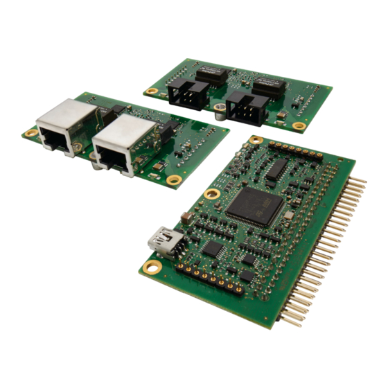
Product description Product description General product description The MC 5004 products are unhoused versions of the FAULHABER Motion Controllers and control either DC, LM or BL motors. The Motion Controllers are configured here via the FAULHABER Motion Manager softwareV6. The drives can be operated in the network via the CANopen or EtherCAT fieldbus interface. -
Page 13: Product Information
Product description Product information Fig. 2: Designation key 6th edition, 22.05.2023 7000.05060, 6th edition, 22.05.20237000.05060... -
Page 14: Product Variants
The following product variants are possible: MC 5004 P RS/CO MC 5004 P ET The Motion Controller PCBs can be mounted on a motherboard. The FAULHABER mother- board can accommodate up to four Motion Controller PCBs. 3.3.1 Controller PCBs 3.3.1.1... -
Page 15: Pcb With Vertical Plug Connector (Option 5621)
Red (continuously flashing): The drive has switched to a fault state. The output stage will be switched off or has already been switched off. Red (error code): Booting has failed. Please contact FAULHABER Support. Green: Power supply within the permissible range. -
Page 16: Ethercat Pcb
Red (continuously flashing): The drive has switched to a fault state. The output stage will be switched off or has already been switched off. Red (error code): Booting has failed. Please contact FAULHABER Support. Green: Power supply within the permissible range. -
Page 17: Motherboard
Product description 3.3.2 Motherboard Fig. 6: Side view (top), top view (middle) and isometric view (bottom) of the mother- board with vertical connectors 6th edition, 22.05.2023 7000.05060, 6th edition, 22.05.20237000.05060... - Page 18 Product description Fig. 7: Side view (top), top view (middle) and isometric view (bottom) of the mother- board with horizontal connectors 6th edition, 22.05.2023 7000.05060, 6th edition, 22.05.20237000.05060...
- Page 19 Product description On delivery, there are rubber pads in the outer and center holes of the motherboard. These holes are marked in blue in Fig. 6 and Fig. 7. Motion Controller DIP switch: connector RS232 - BUS Active/Inactive Encoder connector (M3) Board Area X RS232 connector (X2) Sensor connector (M2)
- Page 20 Product description Designation Function EtherCAT ribbon cable connector Optional ribbon cable connection DIP switch CAN termination CAN termination resistor (On/Off): On: Termination resistor active Off: Termination resistor inactive DIP switch RS232 active/inactive RS232 net mode (on/off): On: RS232 net mode active ...
-
Page 21: Installation
Installation Installation Only trained experts and instructed persons with knowledge of the following fields may install and commission the Motion Controller: Automation technology Standards and regulations (such as the EMC Directive) Low Voltage Directive Machinery Directive ... -
Page 22: Installation Of Motion Controller Pcbs
Installation DANGER! During operation, the drive system produces mechanical forces and movements. Protect the drive system and components driven by the drive system from being touched. 4.1.2 Installation of Motion Controller PCBs Fig. 10: Installation of a Motion Controller PCB NOTICE! Incorrect installation can damage the Motion Controller. -
Page 23: Electrical Connection
For applications with high load inertia, the FAULHABER Braking Chopper of the BC 5004 series can be used to limit overvoltages and thereby protect the power supply. For more detailed information see the data sheet for the Braking Chopper. -
Page 24: Drive Connections
Installation 4.2.2 Drive connections The maximum length of the cable between the Motion Controller and motor depends on the sensor system used and the electrical and magnetic fields in the environment. Tab. 8: Guide values for the cable length Encoder type Unshielded length Shielded length Digital Hall sensors... -
Page 25: Power Supply
Installation 4.2.3.1 Power supply Connect the Motion Controller to a sufficiently dimensioned power supply unit. During acceleration procedures, current peaks with values up to the peak current limit setting of the motor can occur for multiples of 10 ms. ... - Page 26 Installation Designation Meaning Sens A / SIN(+) Hall sensor A / sine signal (sin/cos sensor) Sens B / COS(+) Hall sensor B / cosine signal (sin/cos sensor) Sens C / n.c Hall sensor C / – Supply connection for sensors Ground connection Channel A Encoder channel A...
-
Page 27: Pin Assignment Of The Motherboard (Motor Side)
Installation 4.2.4.2 Pin assignment of the motherboard (motor side) Motor connection (M1) Tab. 10: Pin assignment of the BL motor connection (M1) Designation Meaning Motor A Connection of motor, phase A Motor B Connection of motor, phase B Motor C Connection of motor, phase C Tab. - Page 28 COS(+) Cosine signal SIN(+) Sine signal n.c. – Only in combination with sin/cos sensors on FAULHABER LM motors or BX4 motors in sin/cos special version. Tab. 16: Electrical data of the sensor connection (M2) Designation Value Sensor power supply <100 mA Sensor connection <5 V...
- Page 29 Installation Encoder connection (M3) The pin assignment of the encoder connector varies depending on the encoder type. Incremental encoder with or without line driver Absolute encoder with or without line driver. Tab. 17: Pin assignment for incremental encoder with line driver (M3) Designation Meaning Power supply for incremental encoder...
- Page 30 Installation Tab. 20: Electrical data for incremental encoder without line driver (M3) Designation Value Power supply for incremental encoder <100 mA Connection of the incremental <5 V encoder <2 MHz 5 kΩ Tab. 21: Pin assignment for absolute encoder with line driver (M3) Designation Meaning Power supply for absolute encoder...
- Page 31 Installation Tab. 24: Electrical data for absolute encoder without line driver (M3) Designation Value Absolute encoder power supply <100 mA Connection Chip Select Connection data <5 V 5 kΩ Connection clock 1 MHz COM port (X2) The pin assignment of the COM connection differs according to the type of communication. The distinction is made between the following types of communication: RS232 ...
-
Page 32: Pin Assignment Of The Motherboard (Supply Side)
Installation 4.2.4.3 Pin assignment of the motherboard (supply side) I/O connection (X3) Tab. 27: Pin assignment of the I/O connection (X3) Designation Meaning Power supply for external consumer loads Ground connection 16 14 12 10 8 6 4 2 DigOut 1 Digital output (open collector) DigOut 2 Digital output (open collector) - Page 33 Installation Voltage supply of the controller (X4) Tab. 29: Pin assignment for the power supply of the controller (X4) Designation Meaning Ground connection Power supply for controllers Tab. 30: Electrical data for the voltage supply (X4) Designation Value Power supply for controller 12–50 V ≤100 mA (without external consumer) Power supply of the motor (X5)
-
Page 34: Motherboard: Connection At The Motor Side
Installation EtherCAT port (IN/OUT) Tab. 33: Pin assignment EtherCAT (IN/OUT), connector: RJ45 Designation Meaning IN/OUT EtherCAT communication Pin 1: TxD+ Transmission Data + Pin 2: TxD– Transmission Data – Pin 3: RxD+ Receiver Data + Pin 6: RxD– Receiver Data – Tab. - Page 35 Installation Motor + Motor + DC-Motor Motor – Motor – +5 V Encoder Supply 1 3 5 7 Channel A Encoder Channel A Channel A Encoder Channel A Encoder Channel B Encoder Channel B 2 4 6 8 Channel B Encoder Channel B Index Encoder Index...
- Page 36 Installation Motor A Motor Phase A BL-Motor Motor Phase B Motor B Motor C Motor Phase C +5 V Power Supply Sens A Hall Sensor A Sens B Hall Sensor B Sens C Hall Sensor C +5 V Encoder Supply 1 3 5 7 Channel A Encoder Channel A...
- Page 37 Installation Motor A Motor Phase A Motor B Motor Phase B BL-Motor Motor Phase C Motor C +5 V Power Supply Sens A Hall Sensor A Sens B Hall Sensor B Sens C Hall Sensor C +5 V Power Supply 1 3 5 7 Data Data...
-
Page 38: I/O Circuit Diagrams
Installation 4.2.6 I/O circuit diagrams AGND – AnIn Fig. 19: Analog input circuit diagram (internal) So that the voltage drop on the supply side does not affect the speed specification value, connect the analog input ground (AGND) to the power supply ground (GND). The analog inputs are executed as differential inputs. -
Page 39: External Circuit Diagrams
Installation DigOut DigOut Fig. 21: Digital output circuit diagram (internal) The digital output has the following properties: Open collector switch to ground Monitored output current (switch opens in the event of an error) A digital output can be assigned to an error output. It can be freely programmed. 4.2.7 External circuit diagrams Bipolar analog set-point specification via potentiometer... - Page 40 Installation Analog set-point specification via potentiometer with internally set offset and scaling Motion Controller AnIn AGND – Interface Fig. 23: Analog set-point specification via potentiometer with internally set offset and scaling Connection of reference and limit switches Motion Controller DigIn X DigIn Y Limit Switch Interface...
- Page 41 Installation Connection of an external incremental encoder 2,7k DigIn1 DigIn2 Quadrature Encoder Counter DigIn3 Index Index Interface Fig. 25: Connection of an external incremental encoder Depending on the type of encoder it may be necessary to use additional pull-up resis- tors.
- Page 42 Installation Wiring with several Motion Control Systems in RS232 network operation PC or Node 1 Node n High Level Control 4,7k Fig. 27: Wiring with several Motion Control Systems in RS232 network operation Depending on the number of networked Motion Control Systems, a smaller value may be necessary for the pull-down resistor.
-
Page 43: Electromagnetic Compatibility (Emc)
Installation Electromagnetic compatibility (EMC) Follow the instructions in the following chapters to perform an EMC-compliant installa- tion. WARNING! The Motion Controller can cause high-frequency interference which can affect the function of electronic implants and other electronic devices. Take appropriate interference suppression measures, particularly during use in residen- tial environments. - Page 44 Installation AC-mains system Power adapter Filter Control Filter Motor Line Motor filter filter filter PELV Fig. 30: Interference sources in an AC-mains system Mains impedance of mains transformer – power supply connection Common-mode impedance of electronics on DC side Common-mode impedance of electronics on AC side – power supply connection Impedance of motor housing –...
-
Page 45: Functional Earthing
Installation Problem solutions The interference may vary depending on load and installation. Solution Mode of action Benefits Disadvantages Removes RF common- Does not remove all inter- 3-phase common-mode Removes common-mode mode interference ference choke / ferrite ring around interference of the ... -
Page 46: Cable Routing
Installation 4.3.3 Cable routing WARNING! Voltages >25VAC are generated and transmitted in the drive system. Set up the wiring of the drive system in a touch-proof manner. Only operate the drive system on an SELV or PELV power supply network. The cable routing depends on various factors, such as: Is the cable shielded, twisted? ... -
Page 47: Shielding
Installation 4.3.4 Shielding Shield cables in all cases. Shield cables that are longer than 3 m with tightly meshed copper braiding. Shield all supply lines according to current guidelines/standards (e.g., IPC-A-620B) and connect using (round) shield clamp. In special cases (e.g., with pigtail) or after qualification, the shield can be omitted for the following cables: Cables with length <50 cm ... -
Page 48: Establishing The Shield Connection
Installation 4.3.4.1 Establishing the shield connection The best results when establishing a shield connection on the cable are achieved in the fol- lowing way: Fig. 34: Motor cable shield connection Outer cable shield Heat-shrink tubing Braided shield Crimp-sleeve Shield clamp 1. -
Page 49: Establishing Shield Connection With Cable Lug
Installation 4.3.4.2 Establishing shield connection with cable lug A shield connection with cable lug should be avoided whenever possible. If it is necessary, however, the connection should be established as follows. Fig. 35: Shield connection with cable lug Screw Lock washer Wall Spring washer Wire eyelet... -
Page 50: Sensor And Encoder Interfaces
The sensor systems used at FAULHABER for angle determination should be divided accord- ing to their useful frequency range. Depending on the frequency range, various filter meas- ures are suitable. -
Page 51: Analog Sensors And Analog Hall Sensors
Installation 4.3.5.1 Analog sensors and analog Hall sensors Where possible, shield analog sensor cables and lay them apart from (shielded) motor cables. Connect the shield on one end, ideally on the motor side. The signal quality can be improved with a capacitor (470 nF, dielectric strength > 100 V) between device shield and sensor supply (+5 V). -
Page 52: Using Filters
Motor-side filters: filters that are connected between controller and motor in the motor phases EFS 5005 6501.00350 EFS 3004 6501.00367 EFM 5001/5003/5008 6501.00352 6501.00357 6501.00358 EFC 5008 6501.00351 Fig. 37: Filter categories from FAULHABER 6th edition, 22.05.2023 7000.05060, 6th edition, 22.05.20237000.05060... -
Page 53: Installing The Motion Controller Pcb In The Top-Hat-Rail Housing
Installation 4.3.6.1 Installing the Motion Controller PCB in the top-hat-rail housing The test setup in Fig. 38 shows an example for a Motion Controller PCB installed in a top- hat-rail housing. Fig. 38: Example for installation in a top-hat-rail housing Motion Controller PCB Motor-side filter Motherboard... -
Page 54: Pwm Filter (Motor-Side)
DC power supply 4.3.6.5 Insulation resistance The filters from FAULHABER are not intended for an insulation resistance test. Discharging of the common-mode interference with capacitors prevents a meaningful result from an insulation resistance test. -
Page 55: Coiling Ferrite Ring
Installation 4.3.6.6 Coiling ferrite ring Ideally, ferrites made of manganese-zinc material are used that are active in the 1…10 MHz range. Typical diameters are between 25 and 35 mm onto which two to three windings with all 3 motor phases are wound simultaneously. Fig. -
Page 56: Error Avoidance And Troubleshooting
Installation 4.3.7 Error avoidance and troubleshooting 1. Can the problem clearly be traced back to the FAULHABER drive system? a) Switch the output stage off and on. The voltage controller mode is suitable here. b) Unplug controller supply voltages or operate controller via a separate external power supply used solely for this purpose. - Page 57 Installation Conformity measurements The following points must be observed during the conformity measurement: Conducted interference voltage measurement Radiated interference voltage measurement When laying cables, remove all loops. Where possible, lay cables over a grounding plate. Lay the cables with a meandering shape. ...
-
Page 58: Maintenance And Diagnostics
Maintenance and diagnostics Maintenance and diagnostics Maintenance tasks The drive is generally maintenance-free. Where the device is mounted in a cabinet, depend- ing on the deposition of dust the air filter should be regularly checked and cleaned if neces- sary. Diagnosis Standard PCB and PCB with vertical plug connector Power LED... - Page 59 Red (continuously flashing): The drive has switched to a fault state. The output stage will be switched off or has already been switched off. Red (error code): Booting has failed. Please contact FAULHABER Support. Green: Power supply within the permissible range. Power LED Off: Power supply out of the permissible range.
-
Page 60: Troubleshooting
Maintenance and diagnostics Troubleshooting If unexpected malfunctions occur during operation according to the intended use, please contact your support partner. 6th edition, 22.05.2023 7000.05060, 6th edition, 22.05.20237000.05060... -
Page 61: Accessories
Accessories Accessories Details of the following accessory parts can be found in the Accessories Manual: Connection cables Connectors Connector sets Installation aids Additional equipment 6th edition, 22.05.2023 7000.05060, 6th edition, 22.05.20237000.05060... -
Page 62: Warranty
Warranty Warranty Products of the company Dr. Fritz Faulhaber GmbH & Co. KG are produced using the most modern production methods and are subject to strict quality inspections. All sales and deliv- eries are performed exclusively on the basis of our General Conditions of Sale and Delivery which can be viewed on the FAULHABER home page www.faulhaber.com/gtc and down-... -
Page 63: Additional Documents
Additional documents Additional documents Declaration of Conformity 6th edition, 22.05.2023 7000.05060, 6th edition, 22.05.20237000.05060... - Page 64 Additional documents 6th edition, 22.05.2023 7000.05060, 6th edition, 22.05.20237000.05060...
-
Page 65: Declaration Of Incorporation
Additional documents Declaration of Incorporation 6th edition, 22.05.2023 7000.05060, 6th edition, 22.05.20237000.05060... - Page 66 DR. FRITZ FAULHABER GMBH & CO. KG Antriebssysteme Faulhaberstraße 1 71101 Schönaich • Germany Tel. +49(0)7031/638-0 Fax +49(0)7031/638-100 info@faulhaber.de www.faulhaber.com 7000.05060, 6th edition, 22.05.2023 © Dr. Fritz Faulhaber GmbH & Co. KG...