Table of Contents
Advertisement
Quick Links
Advertisement
Table of Contents
Troubleshooting

Related Manuals for Faulhaber MC 3001 B


Summary of Contents for Faulhaber MC 3001 B
- Page 1 Technical Manual MC 3001 B/P WE CREATE MOTION...
- Page 2 Dr. Fritz Faulhaber GmbH & Co. KG. This document has been prepared with care. Dr. Fritz Faulhaber GmbH & Co. KG cannot accept any liability for any errors in this document or for the consequences of such errors. Equally, no liability can be accepted for direct or consequential damages resulting from improper use of the equipment.
-
Page 3: Table Of Contents
Content About this document ....................... 5 Validity of this document ..................5 Associated documents .................... 5 Using this document ....................5 List of abbreviations ....................6 Symbols and designations ..................7 Safety ..........................8 Intended use ......................8 Safety instructions ....................9 Environmental conditions .................. - Page 4 Content 4.3.5 Sensor and encoder interfaces ............. 72 4.3.5.1 Analogue sensors and analogue Hall sensors ...... 73 4.3.5.2 Incremental encoders / Digital Hall sensors / Digital sensors ................ 73 4.3.5.3 Encoders with absolute interface ......... 73 4.3.6 Using filters ................... 73 4.3.6.1 EMC-compliant mounting of the Motion Controller with motherboard................
-
Page 5: About This Document
About this document About this document Validity of this document This document describes the installation and use of the FAULHABER MC 3001 series. This document is intended for use by trained experts authorised to perform installation and electrical connection of the product. -
Page 6: List Of Abbreviations
About this document List of abbreviations Abbreviation Meaning Alternating Current Absolute encoder AGND Analogue Ground AnIn Analogue input Controller Area Network CAN_L CAN-Low CAN_H CAN-High Clock Chip Select DigIn Digital input DigOut Digital output Electronics Filter Motor Electronics Filter Supply Electromagnetic compatibility Electrostatic discharge Ground... -
Page 7: Symbols And Designations
About this document Symbols and designations CAUTION! Hazards due to hot surfaces. Disregard may lead to burns. Measures for avoidance NOTICE! Risk of damage. Measures for avoidance Instructions for understanding or optimising the operational procedures Pre-requirement for a requested action 1. -
Page 8: Safety
Safety Safety Intended use The Motion Controllers described here are designed for use as slaves for control and posi- tioning tasks for the following motors: DC-Micromotors Linear DC-Servomotors Brushless DC-motors The Motion Controller is suitable in particular for tasks in the following fields of applica- tion: ... -
Page 9: Safety Instructions
Safety Safety instructions NOTICE! Electrostatic discharges can damage the electronics. Wear conductive work clothes. Wear an earthed wristband. NOTICE! Foreign bodies can damage the electronics. Keep foreign objects away from the electronics. NOTICE! Inserting and withdrawing connectors whilst supply voltage is applied at the device can damage the electronics. -
Page 10: Ec Directives On Product Safety
Safety EC directives on product safety The following EC directives on product safety must be observed. If the Motion Controller is being used outside the EU, international, national and regional directives must be also observed. Machinery Directive (2006/42/EC) The controllers with attached motor described in these installation instructions may be drive systems according to the Machinery Directive. -
Page 11: Product Description
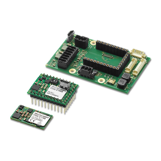
(MC 3001 B) or a 28-pin plug connector (MC 3001 P). With the integrated output stage with optimised current measurement, DC, BL and LM motors from the FAULHABER product line from 06 to 30 mm can be controlled. The following connections are available on the connector strip: Communications interfaces ... -
Page 12: Product Information
Product description Product information … … … … Serial interface RS232 Interface CANopen PCB version with pin terminals PCB version with micro board-to-board connectors 0 : 1 Max. continuous output current 1 A Max. power supply 30 V Motion Controller Fig. -
Page 13: Product Variants
The following product variants are possible: MC 3001 B RS/CO MC 3001 P RS/CO The Motion Controller PCBs can be mounted on a motherboard. The FAULHABER mother- board offers space for a Motion Controller PCB. 3.3.1 Controller PCBs 3.3.1.1... - Page 14 Product description Pin assignment of the connector The MC 3001 B Motion Controller has 3 connectors by means of which the connection between Motion Controller and motherboard or customer-specific peripherals is estab- lished. Fig. 3: Pin overview of the micro board-to-board connectors of the MC 3001 B For technical data, see motherboard pin assignment.
- Page 15 Product description Designation Meaning USB VCC USB port VCC 23…31 Reserved Do not connect 32, 33 Power supply of the electronics 34, 35 Ground connection Power supply of the motor Tab. 3: Pin assignment of connector B Designation Meaning 5V supply connection for sensors 2…4 Ground connection 5…7...
- Page 16 Product description Tab. 4: Pin assignment of connector C Designation Meaning n.c. – 2…5 Reserved Do not connect 6…9 Ground connection 10…13 Phase B Motor phase B 14…17 Ground connection 18…28 Phase B Motor phase B 29…34 Reserved Do not connect Phase C Motor phase C Phase A...
-
Page 17: Standard Pcb With Plug Connectors (Mc 3001 P)
The drive has switched to a fault state. The output stage will be switched off or has flashing) already been switched off. Red (error code) Boot procedure failed. Please contact FAULHABER Support. USB (X1) Connection of the USB communication (USB micro B). 1st edition, 12.02.2021 7000.05071, 1st edition,... - Page 18 Product description Pin assignment of the plug connector The MC 3001 P Motion Controller has a connector strip by means of which the connection between Motion Controller and motherboard or customer-specific peripherals is estab- lished. Fig. 5: Pin overview of the plug connector of the MC 3001 P For technical data, see motherboard pin assignment.
- Page 19 Product description Designation Meaning Index Index channel (logically inverted signal) Index Index channel Channel B Encoder channel B Channel A Encoder channel A Sens C Hall sensor C Sens B Hall sensor B Sens A Hall sensor A 5V supply connection for sensors Phase C Motor phase C Phase B...
-
Page 20: Motherboards
Product description 3.3.2 Motherboards The following motherboards are available and each support both products MC 3001 B and MC 3001 P: Tab. 7: Available motherboards from FAULHABER Option Description Reference 6500.01802 MB1 MC 3001 for general combination with BL/DC-motors including Hall chap. - Page 21 Details: 34-pin + 2-pin edge contact, contact spacing 0.35 mm, gold-plated Manufacturer 505413-3410 number: For each MC 3001 B, 3 sockets are needed. Also observe the dimensions and tolerances shown in the following figures. ± 0.03 1.28 ± 0.03 0.18 ±...
-
Page 22: Motherboard 6500.01802
Product description 3.3.2.2 Motherboard 6500.01802 With this motherboard, it is possible to combine FAULHABER BL/DC-motors as well as Hall sensors and/or encoders. Fig. 7: Side view (top), top view (middle) and isometric view (bottom) of the motherboard 6500.01802 1st edition, 12.02.2021 7000.05071, 1st edition,... - Page 23 Connector overview of the motherboard 6500.01802 Designation Function A, B, C (controller) MC 3001 B connection (for pin assignment, see chap. 3.3.1.1, p. 13) MC (controller) MC 3001 P connection (for pin assignment, see chap. 3.3.1.2, p. 17) M1 (motor)
- Page 24 Product description Tab. 11: Pin assignment of the DC motor connection (M1) Designation Meaning Motor + Connection of motor, positive pole Motor – Connection of the motor, negative pole Tab. 12: Electrical data of the DC motor connection (M1) Designation Value Motor power supply 0...U...
- Page 25 Product description Encoder connection (M3) The pin assignment of the encoder connector varies depending on the encoder type. Incremental encoder with or without line driver Absolute encoder with or without line driver. Tab. 16: Pin assignment for incremental encoder with line driver (M3) Designation Meaning Power supply for incremental encoder...
- Page 26 Product description Tab. 19: Electrical data for incremental encoder without line driver (M3) Designation Value Power supply for incremental encoder <100 mA Connection of the incremental <5 V encoder <2 MHz 5 kΩ Tab. 20: Pin assignment for absolute encoder with line driver (M3) Designation Meaning Power supply for absolute encoder...
- Page 27 Product description Tab. 23: Electrical data for absolute encoder without line driver (M3) Designation Value Absolute encoder power supply <100 mA Connection Chip Select Connection data <5 V 5 kΩ Connection clock 1 MHz USB (X1) Tab. 24: USB port Designation Meaning USB communication (USB micro B)
- Page 28 Product description I/O connection (X3) Tab. 27: Pin assignment of the I/O connection (X3) Designation Meaning Power supply for external consumer loads 9 11 13 Ground connection DigOut 1 Digital output (open collector) DigOut 2 Digital output (open collector) DigIn 1 Digital input DigIn 2 Digital input...
-
Page 29: Motherboard 6500.01807
3.3.2.3 Motherboard 6500.01807 With this motherboard, FAULHABER DC-motors can be combined with encoders of types IE2, IEH2 or IEH3(L). Motor connections M+ and M– can be connected here either via con- nector M1 or, with combined cables, via connector M3. - Page 30 Tab. 29: Connector overview of the motherboard 6500.01807 Designation Function A, B, C (controller) MC 3001 B connection (for pin assignment, see chap. 3.3.1.1, p. 13) MC (controller) MC 3001 P connection (for pin assignment, see chap. 3.3.1.2, p. 17) M1 (motor)
- Page 31 Product description Motor and IE2 encoder connection (M3/1) Tab. 32: Pin assignment of the motor and IE2 encoder connection (M3/1) Designation Meaning Motor – Connection of the motor, negative pole 6 5 4 3 2 1 Motor + Connection of motor, positive pole Ground connection Power supply for incremental encoder Channel B...
- Page 32 Product description Motor and IEH3L encoder connection (M3/3) Tab. 36: Pin assignment of the motor and IEH3L encoder connection (M3/3) Designation Meaning Motor – Connection of the motor, negative pole Power supply for incremental encoder Ground connection Motor + Connection of motor, positive pole Channel A Encoder channel A (logically inverted sig- nal)
- Page 33 Product description COM port (X2) The pin assignment of the COM connection differs according to the type of communication. The distinction is made between the following types of communication: RS232 CANopen Tab. 39: Pin assignment of the COM port (X2) for RS232 Designation Meaning RS232 interface transmit direction...
- Page 34 Product description I/O connection (X3) Tab. 41: Pin assignment of the I/O connection (X3) Designation Meaning Power supply for external consumer loads 9 11 13 Ground connection DigOut 1 Digital output (open collector) DigOut 2 Digital output (open collector) DigIn 1 Digital input DigIn 2 Digital input...
-
Page 35: Motherboard 6500.01808
Product description 3.3.2.4 Motherboard 6500.01808 With this motherboard, FAULHABER DC-motors can be combined with encoders of types IE3(L), IER3(L) or IERS3(L). M3/1 M3/2 Fig. 9: Side view (top), top view (middle) and isometric view (bottom) of the motherboard 6500.01808 1st edition, 12.02.2021 7000.05071, 1st edition,... - Page 36 Tab. 43: Connector overview of the motherboard 6500.01808 Designation Function A, B, C (controller) MC 3001 B connection (for pin assignment, see chap. 3.3.1.1, p. 13) MC (controller) MC 3001 P connection (for pin assignment, see chap. 3.3.1.2, p. 17) M1 (motor)
- Page 37 Product description IE3 encoder connection (M3/1) Tab. 46: Pin assignment of the IE3 encoder connection (M3/1) Designation Meaning – n.c. 6 5 4 3 2 1 Index Encoder index Ground connection Power supply for incremental encoder Channel B Encoder channel B Channel A Encoder channel A Tab.
- Page 38 Product description USB (X1) Tab. 50: USB port Designation Meaning USB communication (USB micro B) COM port (X2) The pin assignment of the COM connection differs according to the type of communication. The distinction is made between the following types of communication: ...
- Page 39 Product description I/O connection (X3) Tab. 53: Pin assignment of the I/O connection (X3) Designation Meaning Power supply for external consumer loads 9 11 13 Ground connection DigOut 1 Digital output (open collector) DigOut 2 Digital output (open collector) DigIn 1 Digital input DigIn 2 Digital input...
-
Page 40: Motherboard 6500.01809
Product description 3.3.2.5 Motherboard 6500.01809 With this motherboard, FAULHABER DC-motors can be combined with encoders of types PA2-100 or HEM3. M3/1 M3/2 Fig. 10: Side view (top), top view (middle) and isometric view (bottom) of the motherboard 6500.01809 1st edition, 12.02.2021 7000.05071, 1st edition,... - Page 41 Tab. 55: Connector overview of the motherboard 6500.01809 Designation Function A, B, C (controller) MC 3001 B connection (for pin assignment, see chap. 3.3.1.1, p. 13) MC (controller) MC 3001 P connection (for pin assignment, see chap. 3.3.1.2, p. 17) M3/1 (motor and controller)
- Page 42 Product description Motor and PA2-100 encoder connection (M3/2) Tab. 58: Pin assignment of the motor and PA2-100 encoder connection (M3/2) Designation Meaning Motor + Connection of motor, positive pole 1 3 5 Motor + Connection of motor, positive pole Power supply for incremental encoder Channel A Encoder channel A Channel B...
- Page 43 Product description COM port (X2) The pin assignment of the COM connection differs according to the type of communication. The distinction is made between the following types of communication: RS232 CANopen Tab. 61: Pin assignment of the COM port (X2) for RS232 Designation Meaning RS232 interface transmit direction...
- Page 44 Product description I/O connection (X3) Tab. 63: Pin assignment of the I/O connection (X3) Designation Meaning Power supply for external consumer loads 9 11 13 Ground connection DigOut 1 Digital output (open collector) DigOut 2 Digital output (open collector) DigIn 1 Digital input DigIn 2 Digital input...
-
Page 45: Motherboard 6500.01810
Product description 3.3.2.6 Motherboard 6500.01810 With this motherboard, FAULHABER 0824B- and 1028B-BL-motors can be combined with encoders of types AESM or IEM3. M3/2 M3/1 Fig. 11: Side view (top), top view (middle) and isometric view (bottom) of the motherboard 6500.01810 1st edition, 12.02.2021... - Page 46 Tab. 65: Connector overview of the motherboard 6500.01810 Designation Function A, B, C (controller) MC 3001 B connection (for pin assignment, see chap. 3.3.1.1, p. 13) MC (controller) MC 3001 P connection (for pin assignment, see chap. 3.3.1.2, p. 17) M3/1 (motor and encoder)
- Page 47 Product description Motor and AESM encoder connection (M3/2) Tab. 68: Pin assignment of the motor and AESM encoder connection (M3/2) Designation Meaning Motor C Connection of motor, phase C 1 3 5 Motor B Connection of motor, phase B Motor A Connection of motor, phase A Ground connection Power supply for absolute encoder...
- Page 48 Product description COM port (X2) The pin assignment of the COM connection differs according to the type of communication. The distinction is made between the following types of communication: RS232 CANopen Tab. 71: Pin assignment of the COM port (X2) for RS232 Designation Meaning RS232 interface transmit direction...
- Page 49 Product description I/O connection (X3) Tab. 73: Pin assignment of the I/O connection (X3) Designation Meaning Power supply for external consumer loads 9 11 13 Ground connection DigOut 1 Digital output (open collector) DigOut 2 Digital output (open collector) DigIn 1 Digital input DigIn 2 Digital input...
-
Page 50: Motherboard 6500.01811
Product description 3.3.2.7 Motherboard 6500.01811 With this motherboard, FAULHABER BL/DC-motors can be combined with encoders of types PA2-50 or HXM. M3/1 M3/2 M3/3 Fig. 12: Side view (top), top view (middle) and isometric view (bottom) of the motherboard 6500.01811 1st edition, 12.02.2021 7000.05071, 1st edition,... - Page 51 Tab. 75: Connector overview of the motherboard 6500.01811 Designation Function A, B, C (controller) MC 3001 B connection (for pin assignment, see chap. 3.3.1.1, p. 13) MC (controller) MC 3001 P connection (for pin assignment, see chap. 3.3.1.2, p. 17) M3/1 (motor and sensors)
- Page 52 Product description Motor and HXM encoder connection (M3/2) Tab. 78: Pin assignment of the motor and HXM encoder connection (M3/2) Designation Meaning Motor – Connection of the motor, negative pole 1 3 5 Ground connection – n.c. Channel B Encoder channel B Channel A Encoder channel A Index...
- Page 53 Product description USB (X1) Tab. 82: USB port Designation Meaning USB communication (USB micro B) COM port (X2) The pin assignment of the COM connection differs according to the type of communication. The distinction is made between the following types of communication: ...
- Page 54 Product description I/O connection (X3) Tab. 85: Pin assignment of the I/O connection (X3) Designation Meaning Power supply for external consumer loads 9 11 13 Ground connection DigOut 1 Digital output (open collector) DigOut 2 Digital output (open collector) DigIn 1 Digital input DigIn 2 Digital input...
-
Page 55: Installation
Installation Installation Only trained experts and instructed persons with knowledge of the following fields may install and commission the Motion Controller: Automation technology Standards and regulations (such as the EMC Directive) Low Voltage Directive Machinery Directive ... -
Page 56: Installation Of Motion Controller Pcbs
Note orientation of the Motion Controller PCB acc. to Fig. 13. MC 3001 B: Connect the Motion Controller PCB (3) to the motherboard (1) using the 3 micro board-to-board connectors (2). MC 3001 P: Connect the Motion Controller PCB (5) to the motherboard (1) using the plug connections (4). -
Page 57: Electrical Connection
For applications with high load inertia, the FAULHABER Braking Chopper of the BC 5004 series in 28 V operation can be used to limit overvoltages and thereby protect the power supply. For more detailed information see the data sheet for the Braking Chopper. -
Page 58: Drive Connections
Installation Motion Drive Controller Neutral point Fig. 14: Potential equalisation between electrically connected parts of the system 4.2.2 Drive connections The maximum length of the cable between the Motion Controller and motor depends on the sensor system used and the electrical and magnetic fields in the environment. Tab. -
Page 59: Connection Of The Power Supply
Installation 4.2.3 Connection of the power supply Discrete inputs and outputs (for instance for discrete set-point specification or for con- nection of limit switches and reference switches) Communication connections Make sure that the connection cables on the connection side are not longer than 3 m. ... -
Page 60: I/O Circuit Diagrams
Installation 4.2.4 I/O circuit diagrams AGND – AnIn Fig. 16: Analogue input circuit diagram (internal) So that the voltage drop on the supply side does not affect the speed specification value, connect the analogue input ground (AGND) to the power supply ground (GND). The analogue inputs are executed as differential inputs. - Page 61 Installation DigOut DigOut Fig. 18: Digital output circuit diagram (internal) The digital output has the following properties: Open collector switch to ground Monitored output current (switch opens in the event of an error) A digital output can be assigned to an error output. It can be freely programmed. 1st edition, 12.02.2021 7000.05071, 1st edition, 12.02.20217000.05071...
-
Page 62: External Circuit Diagrams
Installation 4.2.5 External circuit diagrams Bipolar analogue set-point specification via potentiometer Motion Controller 4,7k AnIn AGND – 20 V 10 V Interface Fig. 19: Bipolar analogue set-point specification via potentiometer Analogue set-point specification via potentiometer with internally set offset and scaling Motion Controller AnIn AGND... - Page 63 Installation Connection of reference and limit switches Motion Controller DigIn X DigIn Y Limit Switch Interface Fig. 21: Connection of reference and limit switches Depending on the type of switch it may be necessary to use additional pull-up resistors. No internal pull-up resistors are incorporated in the Motion Controller. Connection of an external incremental encoder 2,7k DigIn1...
- Page 64 Installation Depending on the type of encoder it may be necessary to use additional pull-up resis- tors. No internal pull-up resistors are incorporated in the Motion Controller. Wiring between PC/controller and a drive PC or Node 1 High Level Control Fig.
-
Page 65: Electromagnetic Compatibility (Emc)
Installation Electromagnetic compatibility (EMC) Follow the instructions in the following chapters to perform an EMC-compliant installa- tion. NOTICE! Drive electronics with qualified limit values in accordance with EN-61800-3: Category C2 can cause radio interference in residential areas. For these drive electronics, take additional measures to limit the spread of radio inter- ference. - Page 66 Installation Parasitic current usually arises from the following components: Semiconductors Capacitive portion of the motor supply line Parasitic elements in the motor Operating the motors with PWM is the cause here. The DC-DC converter in the device and the used switching power supply also produce inter- ference that could affect the mains.
-
Page 67: Functional Earthing
Installation 4.3.2 Functional earthing DANGER! Danger to life through ground leakage currents ≥3.5 mA Check the earthing of the devices for proper installation. The earthing system is essential for discharging parasitic current and for a potential distri- bution in the system that is as uniform as possible. The most efficient systems have a star or mesh shape. - Page 68 Installation Fig. 27: Laying in the cable duct High-current cable Sensor cable Digital cable >5 cm Fig. 28: Grouping and shielding of the cables Shielding Hall sensor Motor phase 1st edition, 12.02.2021 7000.05071, 1st edition, 12.02.20217000.05071...
-
Page 69: Shielding
Installation 4.3.4 Shielding Shield cables in all cases. Shield cables that are longer than 3 m with tightly meshed copper braiding. Shield all supply lines according to current guidelines/standards (e.g., IPC-A-620B) and connect using (round) shield clamp. In special cases (e.g., with pigtail) or after qualification, the shield can be omitted for the following cables: Cables with length <50 cm ... -
Page 70: Establishing The Shield Connection
Installation 4.3.4.1 Establishing the shield connection The best results when establishing a shield connection on the cable are achieved in the fol- lowing way: Fig. 30: Motor cable shield connection Outer cable shield Heat-shrink tubing Braided shield Crimp-sleeve Shield clamp 1. -
Page 71: Establishing Shield Connection With Cable Lug
Installation 4.3.4.2 Establishing shield connection with cable lug A shield connection with cable lug should be avoided whenever possible. If it is necessary, however, the connection should be established as follows. Fig. 31: Shield connection with cable lug Screw Lock washer Wall Spring washer Wire eyelet... -
Page 72: Sensor And Encoder Interfaces
Various solutions for different cable lengths are described in chap. 4.2.2, p. 58. The objec- tive here should be to increase the signal quality to a reliably usable minimum. The sensor systems used at FAULHABER for angle determination should be divided according to their useful frequency range. Depending on the frequency range, various filter measures are suitable. -
Page 73: Analogue Sensors And Analogue Hall Sensors
Input-side filters: filters on the power supply side Motor-side filters: filters that are connected between controller and motor in the motor phases EFS 3004 6501.00367 Fig. 33: Filter categories from FAULHABER 1st edition, 12.02.2021 7000.05071, 1st edition, 12.02.20217000.05071... -
Page 74: Emc-Compliant Mounting Of The Motion Controller With Motherboard
Installation 4.3.6.1 EMC-compliant mounting of the Motion Controller with motherboard The setup in Fig. 34 shows the assembly of a Motion Controller with motherboard. Each of the cable shields is connected to earth potential with low impedance using a shield clamp. Metallisations on screw connections on the PCB must also be connected to earth potential with low impedance (e.g., conductive base plate). -
Page 75: Input-Side Filters
DC power supply 4.3.6.5 Insulation resistance The filters from FAULHABER are not intended for an insulation resistance test. Discharging of the common-mode interference with capacitors prevents a meaningful result from an insulation resistance test. -
Page 76: Error Avoidance And Troubleshooting
Installation 4.3.7 Error avoidance and troubleshooting 1. Can the problem clearly be traced back to the FAULHABER drive system? a) Switch the output stage off and on. The voltage controller mode is suitable here. b) Unplug controller supply voltages or operate controller via a separate external power supply used solely for this purpose. - Page 77 Installation Conformity measurements The following points must be observed during the conformity measurement: Conducted interference voltage measurement Radiated interference voltage measurement When laying cables, remove all loops. Where possible, lay cables over an earth plate. Lay the cables with a meandering shape. Connect the shield of the motor cable on the motor The connection of the motor cable shield is to be as ...
-
Page 78: Maintenance And Diagnostics
Diagnosis Status LED Status LED Fig. 36: Status LED standard PCB MC 3001 B (left) and MC 3001 P (right) Tab. 88: LED overview Designation Function Green (continuous light): Device active. -
Page 79: Accessories
Accessories Accessories Details of the following accessory parts can be found in the Accessories Manual: Connection cables Connector sets Additional equipment Motherboards, see Tab. 7 1st edition, 12.02.2021 7000.05071, 1st edition, 12.02.20217000.05071... -
Page 80: Warranty
Warranty Warranty Products of the company Dr. Fritz Faulhaber GmbH & Co. KG are produced using the most modern production methods and are subject to strict quality inspections. All sales and deliv- eries are performed exclusively on the basis of our General Conditions of Sale and Delivery which can be viewed on the FAULHABER home page https://www.faulhaber.com/gtc and... -
Page 81: Additional Documents
Additional documents Declaration of Conformity EG–Konformitätserklärung EC Declaration of Conformity Dokument-Nr./Monat.Jahr: EG-00016-0001 / 04.2021 Document-No./Month.Year: Dr. Fritz Faulhaber GmbH & Co. KG Der Hersteller: The manufacturer: Daimlerstr. 23/25 D-71101 Schönaich Germany erklärt hiermit, dass das folgende Produkt declares that the following product... - Page 82 Additional documents Anhang A zur Konformitätserklärung Annex A to Declaration of Conformity Dokument-Nr./Monat.Jahr: EG-00016-0001 / 04.2021 Document-No./Month.Year: Die Übereinstimmung mit den genannten EG-Richtlinien wurde durch Überprüfung gemäß nach folgender Fachgrundnorm nachgewiesen: The conformity with the EC guidelines was proven according to the following standards: Fundstelle Ausgabedatum Richtlinienbezug...
-
Page 83: Declaration Of Incorporation
Der Bevollmächtigte für die Zusammenstellung und Übermittlung der relevanten technischen Unterlagen ist: The person responsible for the compilation and transmission of the relevant technical documents is: Dr. Thomas Bertolini, Dr. Fritz Faulhaber GmbH & Co. KG, Daimlerstr. 23/25, 71101 Schönaich, Germany. Schönaich, Dr. - Page 84 DR. FRITZ FAULHABER GMBH & CO. KG Antriebssysteme Daimlerstraße 23 / 25 71101 Schönaich • Germany Tel. +49(0)7031/638-0 Fax +49(0)7031/638-100 info@faulhaber.de www.faulhaber.com 7000.05071, 1st edition, 12.02.2021 © Dr. Fritz Faulhaber GmbH & Co. KG...